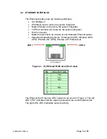
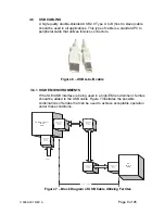
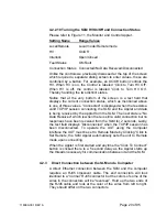

3.3 USB – UNIVERSAL SERIAL BUS INTERFACE
The USB interface has the following attributes:
•
Compliant with USB 1.1 and USB 2.0 specifications
•
Type B male connector
•
Included driver can be communicated with via standard Windows
serial communications methods
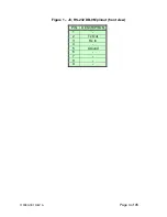
Figure 3 – J4, USB Type B (front view)
PIN
DESCRIPTION
1
Vbus +5V
2
D-
3
D+
4
Ground
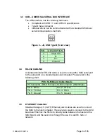
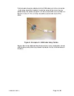
3.4 RS-232
CABLING
A standard shielded RS-232 cable is used to connect the SLM serial port
to the serial port on a standard personal computer. Please refer to the
following chart.
PC to SLM Board Cable Details
PC Connector (DB-9 Female)
SLM Connector (DB-9 Male)
Pin 2: RX In
Pin 2: TX Out
Pin 3: TX Out
Pin 3: RX In
Pin 5: Ground
Pin 5: Ground
3.5 ETHERNET
CABLING
Shielded Category 5 (CAT5) Ethernet patch cables are used to connect
the SLM to the host computer. There are two ways to connect to the SLM
board via Ethernet: the first is to directly cable between the host and the
SLM board, and the second is through the use of a switch, hub, or
network.
118080-001 REV A
Page 6 of 95
Содержание SLM SERIES
Страница 15: ...SLM MANUAL 6 118073 001 Rev C Figure 2 2 Unit Dimensions 1200W ...
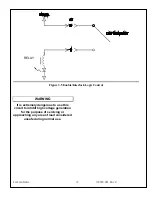
Страница 19: ...SLM MANUAL 10 118073 001 Rev C Figure 3 3 Local Programming via External Voltage Source ...
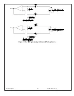
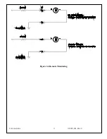
Страница 20: ...SLM MANUAL 11 118073 001 Rev C Figure 3 4 Remote Monitoring ...
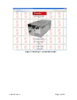
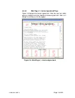
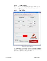
Страница 40: ...Figure 9 Web Page 1 Contact Information 118080 001 REV A Page 13 of 95 ...
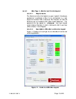
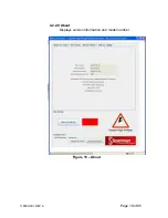
Страница 46: ...4 2 2 9 About Displays version information and model number Figure 15 About 118080 001 REV A Page 19 of 95 ...
Страница 98: ...Request Faults 68 20 ASCII 118080 001 REV A Page 71 of 95 ...


