
SLM MANUAL
4
118073-001 Rev C
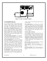
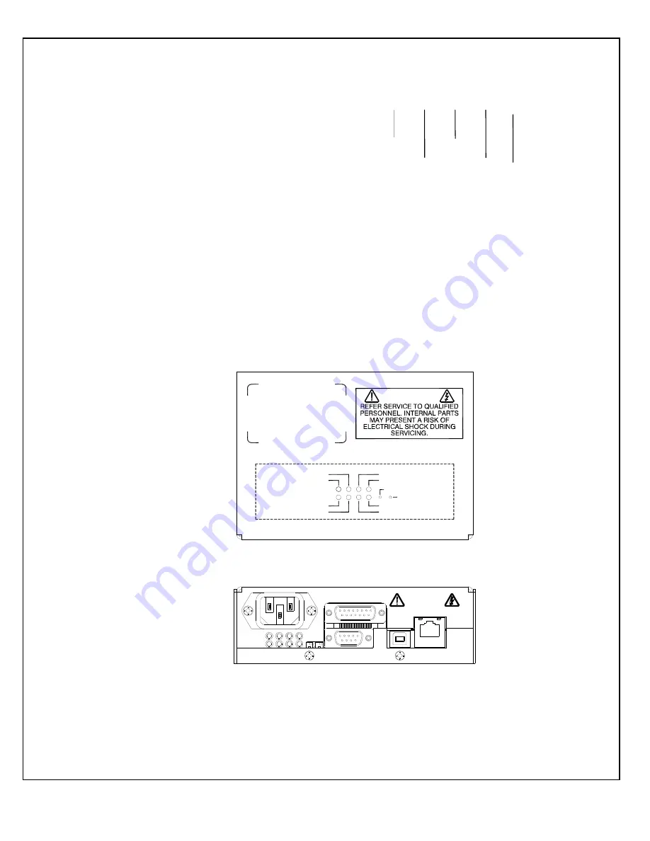
Power On LED:
When the input power is applied to
the unit it is indicated by PWR ON LED status on the
front panel.
I MODE:
Indicates the output current regulator
circuit is maintaining current regulation.
This is
indicated by I Mode LED status on the front panel
and via RS-232, USB or Ethernet as I Mode.
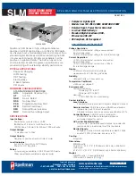
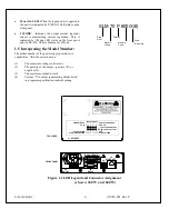
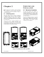
1.5 Interpreting the Model Number:
The model number of the power supply describes its
capabilities. After the series name is:
(1)
The maximum voltage in kilovolts.
(2)
The polarity of the output – positive (P), or
negative (N).
(3)
The maximum output in watts.
(4)
Custom “X” number representing details listed
in a separate specification control drawing.
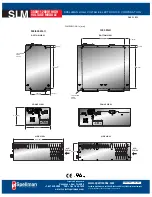
J2 CONTROL I/O
ETHERNET
J4
USB
J5
J3
RS232
J6
HV OUT
TOP COVER
FRONT PANEL
WARNING
OVER VOLTAGE
ARC
REGULATION ERROR
LOCAL CURRENT ADJ
LOCAL VOLT ADJ
STATUS LIGHTS
PWR ON
J1 AC INPUT
OVER TEMPERATURE
OVER CURRENT
CURRENT MODE
HV 0N
Figure 1.1 LED Legend and Connector Assignment
(shown 300W and 600W)
SLM 70 P 600/X(#)
Serie
Nam
Voltag
Maximu
Polarity
"X" Number
Custo
Powe
Maximu
Содержание SLM SERIES
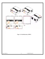
Страница 15: ...SLM MANUAL 6 118073 001 Rev C Figure 2 2 Unit Dimensions 1200W ...
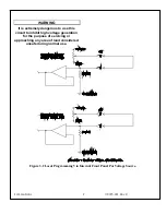
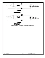
Страница 19: ...SLM MANUAL 10 118073 001 Rev C Figure 3 3 Local Programming via External Voltage Source ...
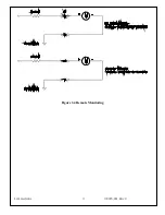
Страница 20: ...SLM MANUAL 11 118073 001 Rev C Figure 3 4 Remote Monitoring ...
Страница 40: ...Figure 9 Web Page 1 Contact Information 118080 001 REV A Page 13 of 95 ...
Страница 46: ...4 2 2 9 About Displays version information and model number Figure 15 About 118080 001 REV A Page 19 of 95 ...
Страница 98: ...Request Faults 68 20 ASCII 118080 001 REV A Page 71 of 95 ...


