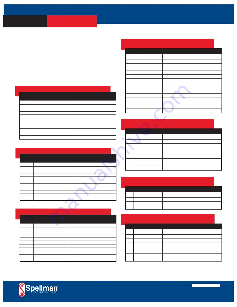
ETHERNET DIGITAL INTERFACE—
J5 8 PIN RJ45 CONNECTOR
PIN
SIGNAL
SIGNAL PARAMETERS
1
TX+
Transmit Data +
2
TX-
Transmit Data -
3
RX+
Receive Data +
4
NC
No Connection
5
NC
No Connection
6
RX-
Receive Data -
7
NC
No Connection
8
NC
No Connection
PAGE 2 OF 3
SLM SELECTION TABLE- 300W
300 Watt
kV
mA
Model
1
300
SLM1*300
3
100
SLM3*300
5
60
SLM5*300
10
30
SLM10*300
15
20
SLM15*300
20
15
SLM20*300
30
10
SLM30*300
40
7.5
SLM40*300
50
6
SLM50*300
60
5
SLM60*300
70
4.28
SLM70*300
RS-232 DIGITAL INTERFACE—
J3 9 PIN FEMALE D CONNECTOR
PIN
SIGNAL
SIGNAL PARAMETERS
1
NC
No Connection
2
TX out
Transmit Data
3
RX in
Receive Data
4
NC
No Connection
5
SGND
Ground
6
NC
No Connection
7
NC
No Connection
8
NC
No Connection
9
NC
No Connection
*Specify “P” for positive polarity or “N” for negative polarity
USB DIGITAL INTERFACE—
J4 4 PIN USB “B” CONNECTOR
PIN
SIGNAL
SIGNAL PARAMETERS
1
VBUS
+5 Vdc
2
D-
Data -
3
D+
Data +
4
GND
Ground
SLM ANALOG INTERFACE—
J2 15 PIN MALE D CONNECTOR
PIN SIGNAL
SIGNAL PARAMETERS
1
Power Supply Fault
Open Collector, 35V @ 10mA Maximum
2
Current Program In
0 to 10V=0 to 100% Rated Output, Zin=10MΩ
3
Voltage Program In
0 to 10V=0 to 100% Rated Output, Zin=10MΩ
4
NC
No Connection
5
Local Voltage Prog.
Multi-turn front panel potentiometer
6
NC
No Connection
7
Local Current Prog.
Multi-turn front panel potentiometer
8
Voltage Monitor
0 to 10V=0 to 100% Rated Output, Zout =4.99k, 1%
9
Signal Ground
Ground
10
Current Monitor
0 to 10V=0 to 100% Rated Output, Zout =4.99k, 1%
11
HV Enable Input
Connect to Pin 12 to HV Enable Supply
12
HV Enable Output
+15V @ Open, ≤15mA @ Closed
13
NC
No Connection
14
HV On Output Signal
Open Collector, 35V @10mA Maximum
15
Spare
No Connection
SPELLMAN HIGH VOLTAGE ELECTRONICS CORPORATION
300W-1200W HIGH
VOLTAGE MODULE
SLM
SLM SELECTION TABLE- 600W
600 Watt
kV
mA
Model
1
600
SLM1*600
3
200
SLM3*600
5
120
SLM5*600
10
60
SLM10*600
15
40
SLM15*600
20
30
SLM20*600
30
20
SLM30*600
40
15
SLM40*600
50
12
SLM50*600
60
10
SLM60*600
70
8.56
SLM70*600
*Specify “P” for positive polarity or “N” for negative polarity
SLM SELECTION TABLE- 1200W
1200 Watt
kV
mA
Model
1
1200
SLM1*1200
3
400
SLM3*1200
5
240
SLM5*1200
10
120
SLM10*1200
15
80
SLM15*1200
20
60
SLM20*1200
30
40
SLM30*1200
40
30
SLM40*1200
50
24
SLM50*1200
60
20
SLM60*1200
70
17.14
SLM70*1200
*Specify “P” for positive polarity or “N” for negative polarity
Input Line Connector:
IEC320 cord set with integrated EMI filter
Output Cable:
A detachable 10’ (3.3m) long shielded HV cable is provided
Regulatory Approvals:
Compliant to 204/108/EC, the EMC Directive and 2006/95/EC,
the Low Voltage Directive. UL/CUL recognized, File 227588.
Corporate Headquarters
Hauppauge, New York USA
+1-631-630-3000 FAX: +1-631-435-1620
e-mail: [email protected]
www.spellmanhv.com
128035-001 REV. M
Spellman High Voltage is an ISO 9001:2008 and ISO 14001:2004 registered company
Copyright © 2006 Spellman High Voltage Electronics Corp.
Содержание SLM SERIES
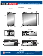
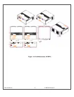
Страница 15: ...SLM MANUAL 6 118073 001 Rev C Figure 2 2 Unit Dimensions 1200W ...
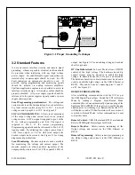
Страница 19: ...SLM MANUAL 10 118073 001 Rev C Figure 3 3 Local Programming via External Voltage Source ...
Страница 20: ...SLM MANUAL 11 118073 001 Rev C Figure 3 4 Remote Monitoring ...
Страница 40: ...Figure 9 Web Page 1 Contact Information 118080 001 REV A Page 13 of 95 ...
Страница 46: ...4 2 2 9 About Displays version information and model number Figure 15 About 118080 001 REV A Page 19 of 95 ...
Страница 98: ...Request Faults 68 20 ASCII 118080 001 REV A Page 71 of 95 ...


