Index
I-5
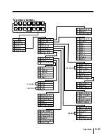
Setup
auxiliary bus control 14-39
chroma key input signal 14-20
DME interface 14-40
GPI inputs 14-43
GPI outputs 14-45
keyers 14-30
matte generator 14-34
operation from control panel
14-51
overall switcher system 14-4
peripheral device interface
14-37
routing switcher interface
14-42
safe title function 14-35
wipes 14-30
Setup data
recall 14-2
saving 14-2, 14-14
SETUP menu A-32
SETUP menu display 14-3
7.5 IRE setup on/off 14-6
SHIFT button 2-11, 2-24, 2-28
Shift function 4-8
SHOT BOX control section 2-35
SHOT BOX menu 14-75
Signal assignment to cross-point
buttons 4-8
Signal format selection 14-6
Signal selection section
M/E banks 2-5
PGM/PST bank 2-18
Single mode 4-85, 5-2
Single mode CHROMA KEY
menu 5-18
Snapshot
attribute setting 9-14
attributes 7-4
information display 4-109
operations 7-6
recalling 7-8
register manipulation 9-7
saving 7-6
types 7-2
SNAPSHOT button 2-12, 2-25
Software
installation 14-5
version number 14-16
Source name display
auxiliary bus bank 2-23
M/E banks 2-7
PGM/PST bank 2-19
Source name indications 4-9
Spot color adjustment 5-30
Standard wipes A-2
Status display 4-104
STATUS menu A-17
Sub-register selection 9-4
Sub-register selection section
2-25
Sub-registers 7-3, 8-7
Subsidiary mask 4-55
Super mix 4-19
Super mix dissolve 4-17
Swap
Keyer swap 11-3
Matte swap 11-3
M/E swap 11-2
Wipe swap 11-3
SWAP 9-4
Switcher
clean output 14-26
function change 14-57
initialization 14-15
input signal 14-19
output signal assignment
14-26
output signal setup 14-22
ports 12-3
resetting 14-15
SWITCHER OUTPUT menu
14-22
System configuration 1-3
SYSTEM menu 14-4
System settings 14-6
SYSTEM SETUP menu 14-6
T
Tablet
connection 12-5
functions controllable 12-7
positioner function control
12-7
settings 12-6
Text input 3-11
Time line display 8-32
Time settings 8-15
Top menu selection buttons 2-28
Trackball 2-33
TRACK BALL menu 14-71
Trackball adjustment 14-71
Transition
control section (M/E banks)
2-8
control section (PGM/PST
bank) 2-20
duration adjustment 4-25
execution 4-23, 4-26
indicator 2-10
limit 4-18
progress indicators 4-23
rate setting 4-24
type selection 4-16
type selection buttons 2-9
U
Upgrade board mode selection
5-15
UTILITY button 14-73
UTILITY menu 14-73
V
Vertical blanking interval
adjustment 14-23
Video signal 5-30
adjustment 5-12
clip values 14-22
Video switching timing 14-6
VTR control data 13-6
VTR INTERFACE menu 14-50
VTR, interface with 13-6
W
White clip value for luminance
signal 14-22
Window adjustment 5-10
Wipe 4-17, 4-64
copy 11-3
direction 4-66
edge softness adjustment
14-33
information display 4-108
modifier resetting 4-82
modifiers 4-74
WIPE button 2-12
WIPE menu 14-33
Содержание DVS-7250
Страница 10: ......
Страница 30: ......
Страница 66: ......
Страница 67: ...Menu Organization 3 2 Basic Menu Operations 3 6 Chapter 3 Basic Menu Operations ...
Страница 274: ......
Страница 328: ......
Страница 347: ...Overview 10 2 Disks and Data Held 10 2 Disk Functions 10 3 Disk Operations 10 4 Chapter 10 Floppy Disk Operations ...
Страница 364: ......
Страница 488: ......
Страница 494: ...A 2 Appendixes Standard Wipes 1 2 3 4 5 6 7 8 9 10 11 12 13 14 15 16 17 18 19 20 22 Wipe Patterns ...
Страница 495: ...Appendixes A 3 Enhanced Wipes 21 23 24 26 27 29 49 300 301 302 303 304 POLYGON ...
Страница 499: ...Appendixes A 7 Random Dust Wipes RANDOM3 DIAMOND DUST RANDOM RANDOM2 270 271 272 RANDOM4 273 274 ...
Страница 534: ......
Страница 542: ...Sony Corporation B P Company BZS 7061A WW A AE0 600 01 1 1999 ...


