2-16
Chapter 2
Location and Function of Parts
Mix/Effects Banks
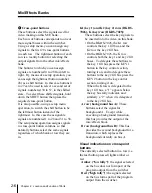
Display
Meaning
C–10
Clip value is –10.
D100
Density value is 100.
7
Edge type selection buttons
Press one of these buttons, turning it on, to
apply a particular modification to the key
edge.
BORD (border): Apply a border around
the key.
DROP BORD: Apply a border in
specified directions (for example
below and to the right or below and to
the left) around the key.
SHDW (shadow): Add a shadow to the
key in specified directions (for
example below and to the right or
below and to the left).
OUTLINE: Use the key outline
function.
• When you apply a border, drop border or
shadow, you can select the edge fill
signal to be inserted in this area, using
either the special-purpose color matte
generator, or an external video signal on
the utility bus.
• When you use the outline function, you
can use the signal selected on the key fill
bus for the edge fill.
You can also adjust the width, position,
softness and density of the edge portion.
8
Key parameter setting knobs and
displays
Turning the knobs allows you to change
various key parameters. The display
below each knob shows the initial letter of
the parameter name and its value (a
maximum of three digits including a minus
sign).
9
PROC (processed) KEY button
When the switcher system has a DME-
7000 or other DME unit connected,
pressing this button, turning it on, allows
you to use the processed key function.
When the processed key function is
enabled, before combination with the
background, the key fill and key source
signals produced by the switcher keyer
(with borders, shadows and other
processing already effected) are output to
the DME from the switcher auxiliary
buses. These signals are subjected to
DME processing to add extra effects, and
then returned to the switcher. Finally the
signals returned from the DME undergo
further processing and are then combined
with the background. Since the same
keyer is used both for the initial processing
and for the processing of the return signals
from the DME, you can use both keyers on
an M/E bank simultaneously, for greater
efficiency.
Содержание DVS-7250
Страница 10: ......
Страница 30: ......
Страница 66: ......
Страница 67: ...Menu Organization 3 2 Basic Menu Operations 3 6 Chapter 3 Basic Menu Operations ...
Страница 274: ......
Страница 328: ......
Страница 347: ...Overview 10 2 Disks and Data Held 10 2 Disk Functions 10 3 Disk Operations 10 4 Chapter 10 Floppy Disk Operations ...
Страница 364: ......
Страница 488: ......
Страница 494: ...A 2 Appendixes Standard Wipes 1 2 3 4 5 6 7 8 9 10 11 12 13 14 15 16 17 18 19 20 22 Wipe Patterns ...
Страница 495: ...Appendixes A 3 Enhanced Wipes 21 23 24 26 27 29 49 300 301 302 303 304 POLYGON ...
Страница 499: ...Appendixes A 7 Random Dust Wipes RANDOM3 DIAMOND DUST RANDOM RANDOM2 270 271 272 RANDOM4 273 274 ...
Страница 534: ......
Страница 542: ...Sony Corporation B P Company BZS 7061A WW A AE0 600 01 1 1999 ...

