background image

Veterinary 3 Parameter 

Advisor® Vital Signs Monitor

WW V9230 Operation Manual

-

 English

Catalog Number V1886R3

Version 0, February 2009

©

 2009 Smiths Medical family of companies. All rights reserved.

NIBP

PRIN

T

ALARM

SILENC

E

ZERO IBP

BATT

ON

OFF

AC

Patient ID

TRENDS

ALARMS

SETUP

QUICKSET SUSPEND

NIBP MODE 

MANUAL

FREEZE

Содержание SurgiVet Advisor WWV9230

Страница 1: ...230 Operation Manual English Catalog Number V1886R3 Version 0 February 2009 2009 Smiths Medical family of companies All rights reserved NIBP PRINT ALARM SILENCE ZERO IBP BATT ON OFF AC Patient ID TRENDS ALARMS SETUP QUICKSET SUSPEND NIBP MODE MANUAL FREEZE ...

Страница 2: ......

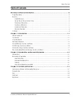
Страница 3: ...nventions 1 1 Using the Manual 1 1 Definition of Symbols 1 2 General Warnings Cautions and Notes 1 3 ECG Warnings Cautions and Notes 1 6 Oximetry Warnings Cautions and Notes 1 7 Non invasive Blood Pressure Warnings Cautions and Notes 1 8 Chapter 2 Intended Use and General Information 2 1 Intended Use 2 1 Measurement Capabilities 2 1 Heart Pulse Rate 2 1 Electrocardiography ECG 2 1 Oximetry 2 1 Non...

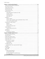
Страница 4: ...e the Units of Measurement 4 6 Bed Name 4 6 Parameter Colors 4 7 Change the Parameter Colors 4 7 Software Revisions 4 7 View the Software Revisions Box 4 7 Service Menu 4 8 Time and Date 4 8 Change the Time and Date 4 8 Chapter 5 Monitoring the Patient 5 1 General Monitoring Instructions 5 1 Attach the Patient 5 1 Adjust the Waveforms Settings 5 1 Adjust the Parameter Box Settings 5 2 Set the Alar...

Страница 5: ...ngs Cautions and Notes 7 1 Theory of Operation 7 2 Using the ECG Parameter 7 2 Attaching the Patient 7 2 Choosing the Waveform Settings 7 4 Access the Waveform Menu 7 4 Change the Primary ECG Lead 7 5 Choose the Waveform Size 7 6 Choose the Waveform Speed 7 6 Use Waveforms 2 4 to Display ECG 7 7 Adjusting the Settings in the Parameter Box 7 8 Turn Alarm Detection On or Off 7 8 Choose the Heart Rat...

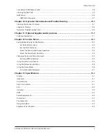
Страница 6: ... Detection On or Off 8 8 Choose the Waveform Speed 8 8 Turn the Peripheral Pulse Rate PPR Display On or Off 8 8 Choose the Averaging Period for the Oximetry Parameter 8 9 Adjusting the Volume of the Heartbeat Beep Tone 8 9 SpO2 Alarms 8 10 Oximetry Alarm Messages 8 11 Chapter 9 Non invasive Blood Pressure 9 1 Using the NIBP Parameter 9 1 Non invasive Blood Pressure Measurement Capability 9 1 Non i...

Страница 7: ...Setting Default Values for the Monitor 12 2 Set Default Alarm Limits 12 2 Set the ECG Filter Level 12 3 Select the Alarm Audio Silence Operation 12 4 Select the Alarm Reset Operation 12 4 Changing the Service Menu Password 12 5 Verifying NIBP Calibration 12 5 Using the Static Limits Feature 12 5 Using the Factory Service Menu 12 6 Using the Demo Mode 12 6 Auto Detectable Parameters 12 7 Chapter 13...

Страница 8: ... Response Time of Heart Rate Meter to Change in Heart Rate A 1 Display Aspect Ratio A 1 Audible Alarms A 1 Visual Alarms A 1 Line Isolation Transients A 1 Electrode Polarization A 1 Audible Alarm Silencing A 2 Appendix B Alarm Limit Defaults B 1 Heart Rate B 1 Oximetry B 1 Non invasive Blood Pressure NIBP B 1 Appendix C IEC 60601 1 2 Requirements 2nd Edition 2001 C 1 Appendix D Revision History D ...

Страница 9: ...Medical family of companies The symbol indicates the trademark is registered in the U S Patent and Trademark Office and certain other countries All other names and marks mentioned are the trade names trademarks or service marks of their respective owners The serial autocorrelation technology in the monitor is covered by U S Patent No 5 558 096 ...

Страница 10: ...Table of Contents viii Veterinary 3 Parameter Advisor Operation Manual This page is intentionally left blank ...

Страница 11: ...manship under normal use if used in accordance with its labeling for 90 days from the date of shipment to the original purchaser USA only Blood pressure cuffs carry a 6 six month warranty pending evaluation by Smiths Medical PM Inc SMPM Technical Services Cuffs that are contaminated have liquid in them have been misused abused or are older than 6 months will not be covered under warranty The sole ...

Страница 12: ...ecommended instructions for use and others Conditions of Warranty This warranty is void of the Product has been altered misused damaged by neglect or accident not properly maintained or recharged or repaired by persons not authorized by Seller Misuse includes but is not limited to use not in compliance with the labeling or use with accessories not manufactured by Seller This warranty does not cove...

Страница 13: ... 262 542 0718 Web www surgivet com Seller will not be responsible for unauthorized returns or for loss or damage to the Product during the return shipment The repaired or replaced Product will be shipped freight prepaid by Seller to Purchaser To obtain warranty information outside the USA contact your local distributor NOTE Shipments received without a return number will be returned to sender Keep...

Страница 14: ...Warranty and Service Information xii Veterinary 3 Parameter Advisor Operation Manual This page is intentionally left blank ...

Страница 15: ...mbered according to the chapter in which they are found such as Figure 7 3 Using the Manual The monitor allows you to choose the measurement capabilities you need A measured value refers to a derived or calculated value a parameter refers to one or more specific measured values For example pulse rate and SpO2 are measurements the Oximeter parameter consists of both these measured values Operation ...

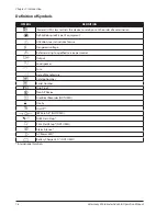
Страница 16: ...F equipment f Attention see instructions for use 1 Dangerous voltage 7 Refer servicing to qualified service personnel D Output 0 Loudspeaker w Fuse y Date of Manufacture Catalog Number Serial Number IPX1 Drip Proof 1 Non AP Device t Graphical Recorder NOT USED 8 Use by x On Off Q IBP Zero All NOT USED h NIBP Start Stop F Print Start Stop NOT USED B Alarm Silence X AC Power LED M Battery Charge LED...

Страница 17: ...to manufacturer s instructions or local regulations Note If applicable EU national or local regulations concerning waste disposal must take precedence over the above advice Keyword Definition Warning Tells you something that could hurt the patient or hurt the operator caution Tells you something that could damage the device note Tells you other important information General Warnings Cautions and N...

Страница 18: ...ted to the monitor s data interface must be certified according to the respective IED standards i e IEC 60950 for data processing equipment or IEC 60601 1 for electro medical equipment All combinations of equipment must be in compliance with IEC 60601 1 1 systems requirements Anyone connecting additional equipment to the signal input port or signal output port configures a medical system and there...

Страница 19: ...onnecting it from the monitor Leaving the AC power supply connected to an AC power outlet without being connected to the monitor may result in a safety hazard WARNING Do not allow any moisture to touch the AC power supply connectors or a safety hazard may result Ensure that hands are thoroughly dry before handling the AC power supply WARNING Do not place the monitor in the patient s bed Do not pla...

Страница 20: ...dinances and recycling instructions regarding disposal and recycling of device components and packaging NOTE All user and patient accessible materials are non toxic NOTE Each input and output connection of the monitor is electrically isolated Connection of this monitor to other equipment will not increase leakage current ECG Warnings Cautions and Notes WARNING Connect only three lead or five lead ...

Страница 21: ...or the patient Use another sensor or patient cable or contact the equipment dealer for help if necessary WARNING Do not autoclave ethylene oxide sterilize or immerse the sensors in liquid Evidence that liquid has been allowed to enter the monitor voids the warranty WARNING Use only SpO2 sensors supplied with or specifically intended for use with this device WARNING SpO2 measurements may be adverse...

Страница 22: ...e measurements may not be accurate for patients experiencing arrhythmias WARNING Do not verify the Non Invasive Blood Pressure calibration while the cuff is attached to a patient WARNING Verify cuff size is correct for the selected patient mode on the monitor CAUTION To ensure that the unit remains in calibration perform a calibration verification on a yearly basis CAUTION Extremity and cuff motio...

Страница 23: ...displayed in the NIBP HISTORY found in the TRENDS menu You can choose the source AUTO ECG or SPO2 of the heart pulse rate displayed in the ECG parameter box If you choose AUTO the monitor will determine the best source depending on the quality of available data and selected source priority See Choose the Heart Rate Source in Chapter 7 ECG for detailed information regarding the source of the heart ...

Страница 24: ...Chapter 2 Intended Use and General Information 2 2 Veterinary 3 Parameter Advisor Operation Manual This page is intentionally left blank ...

Страница 25: ...imits will be reset to their default settings if not in STATIC LIMITS mode NIBP inflation pressure settings will be reset for a cat dog or horse patient For example the default cat NIBP inflation pressure setting is 200 mmHg the default dog NIBP inflation pressure setting is 150 mmHg the default horse NIBP inflation pressure setting is 100 mmHg The NIBP mode will be reset to MANUAL If the alarm li...

Страница 26: ...veform 1 is dedicated to the primary ECG lead although you can specify which lead is to be the primary Waveform 2 can be assigned to another ECG lead in five lead mode only a cascade continuation of the primary ECG lead waveform or a waveform from any other enabled parameter Waveform 3 can be changed to display a cascade continuation of the primary ECG lead waveform after waveforms 1 and 2 or it c...

Страница 27: ... displayed The value may be derived or calculated Dashes in place of a numeric measured value indicate that the measurement is invalid or unavailable High and Low Alarm Limits The high and low alarm limits for the numeric measured values are displayed If you do not set alarm limits for a new patient the default high and low limits will be used Alarm Limit Descriptor The alarm limit descriptor indi...

Страница 28: ...ones within the two minutes press the key again Press the key for 3 seconds to silence alarms indefinitely AUDIO PAUSED will be displayed A new alarm will cancel silence Press the key for 6 seconds to turn alarm sounds off permanently AUDIO OFF will be displayed Rotary Knob The rotary knob is a dial control with a push selection switch It is located on the front of the monitor in the lower right c...

Страница 29: ...rned on If five lead processing is installed on your monitor you must also set the ECG LEADS PROCESSING menu option to five lead processing See Parameter Options in Chapter 4 Setting Up the Monitor for instructions for turning on ECG MONITOR and setting ECG LEADS PROCESSING CAUTION A three lead ECG cable must be used if 3 Lead processing is selected A five lead ECG cable must be used if 5 Lead pro...

Страница 30: ... holder y Voltage Rating The monitor s AC rating is shown If the AC rating does not match the nominal voltage at your installation site do not use the monitor Contact your authorized repair center for help Back Panel connector description instruction u Air Vents The monitor has air vents at the top of the back panel and on the bottom of the monitor Figure 3 5 Back Panel CAUTION DO NOT DISASSEMBLE ...

Страница 31: ...oom with a temperature of 0 40 C 32 104 F and a relative humidity of 15 95 1 non condensing If the monitor was in an area having a temperature higher or lower than this wait a few minutes before a setting up and using the monitor Check the monitor s AC rating Check the monitor s AC rating plate to ensure the nominal voltage at your 2 installation site matches the monitor s rating If the AC rating ...

Страница 32: ... MANUAL If the alarm limits for oximetry were adjusted to below 85 they will be reset to 85 When monitoring a cat or small animal set the monitor to the cat type When monitoring dogs or medium size animals set the monitor to the dog type When monitoring horses or large animals set the monitor to the horse type Figure 4 1 Patient Type Change the Patient Type Turn the rotary knob on the monitor to m...

Страница 33: ...f the display The field may be blank Push the knob to access the patient identification submenu in the lower left corner of the display Highlight DISPLAY and push the knob to select 2 Turn the rotary knob to choose the desired patient information to display BED ONLY BED PATIENT ID BED 3 PATIENT NAME and push the knob to select You can add the bed name on the SETUP MENU See Bed Name in this chapter...

Страница 34: ...ame may be up to 14 characters long Highlight ENTER and push the knob to select 7 Add a Patient s ID On the patient identification submenu turn the rotary knob to highlight PATIENT ID and push the knob to 1 select Turn the rotary knob to access the patient ID box and push the knob to select the first character field 2 Turn the rotary knob to highlight the desired character and push the knob to sel...

Страница 35: ...AUTION A three lead ECG cable must be used if 3 Lead processing is selected A five lead ECG cable must be used if 5 Lead processing is selected Using the incorrect cable for the selected mode might lead to a floating reference or additional noise on the ECG signal Highlight MAIN or PREVIOUS and push the knob to select 5 Turn On or Off Installed Parameters Turn the rotary knob on the monitor to mov...

Страница 36: ...g kPa 0 133 Highlight MAIN or PREVIOUS and push the knob to select 6 Bed Name While specific patient identification information is expected to change the bed or room to which the monitor is assigned may remain the same The BED NAME menu option makes it possible to associate a room or bed with the monitor without respect to any particular patient To change the bed name Turn the rotary knob on the m...

Страница 37: ... the monitor to move the cursor On the main menu at the bottom of the display 1 highlight SETUP and push the knob to select Highlight PARAMETER COLORS and push the knob to select 2 Highlight the desired parameter and push the knob to select 3 Highlight the desired color and push the knob to select 4 To restore the factory default colors turn the rotary knob to highlight RESTORE FACTORY COLORS and ...

Страница 38: ...ower The time and date stamp is used for the NIBP tabular trends the displayed and printed trends and all other printouts The time display format is based on the 24 hour clock For example 5 00 a m is displayed as 5 00 and 5 00 p m is displayed as 17 00 Change the Time and Date Turn the rotary knob on the monitor to move the cursor Highlight the time and date as they are displayed 1 Push the knob t...

Страница 39: ...o the chapters dedicated to each parameter for details regarding sensors and specific parameter box functions Adjust the Waveforms Settings Choose the waveforms to be displayed in positions 2 4 and adjust the settings for each waveform Turn the rotary knob on the monitor to move the cursor Highlight the waveform label and push the knob to access the waveform menu in the lower left corner of the di...

Страница 40: ...rm will be issued The Advisor Vital Signs Monitor provides clinically appropriate default high and low alarm limits for each numeric measured value You can choose different high and low limits depending on the monitoring requirements of each patient For a list of default alarm limits see Appendix B Alarm Limit Defaults WARNING Verify that alarm limits are clinically appropriate for your patient an...

Страница 41: ...m by pressing the alarm silence key B See Select the Alarm Reset Operation in Chapter 12 Service Menu for instructions for choosing AUTO RESET or MANUAL RESET NOTE Only qualified personnel may set the automatic or manual alarm silence or enable indefinite alarm silence See Chapter 12 Service Menu for details regarding alarm reset and silence For MANUAL RESET alarms if the measured value returns to...

Страница 42: ...e knob to select 4 NOTE When you change the patient type or power down this setting will default to ON Alternatively you can preclude additional alarms by adjusting the current high and low alarm limits by using the QUICKSET feature or by setting the limits to OFF in the alarm limits box In some cases the indefinite alarm silence feature may be enabled This will prevent the audible alarm tones fro...

Страница 43: ...10 90 NO CHG 92 10 102 NO CHG High Systolic 138 mmHg Low Systolic No change High Diastolic 90 mmHg Low Diastolic No change High Mean 102 mmHg Low Mean No change Oximetry 98 SpO2 QS HI NO CHG QS LO 5 NO CHG 98 5 93 High No change is made Low 93 NO CHG No Change The newly reset alarm limits will be displayed in the parameter boxes When an alarm occurs and you select QUICKSET VIOLATED ONLY the monito...

Страница 44: ...red values High and low alarm limits as reset using the QUICKSET feature Heart Rate High 20 350 bpm OFF Low OFF 20 350 bpm QS HI 25 QS LO 25 Heart rate 44 beats per minute bpm High 77 Low 20 Since the minimum value for a low alarm limit is 20 27 bpm is not an option 44 25 20 QUICKSET will not reset the low alarm limit to less than 20 or OFF To set the QUICKSET high and low numbers Turn the rotary ...

Страница 45: ... push the knob to select f To use the QUICKSET feature to reset an alarm limit for a measured value that matched or exceeded the existing alarm limit Turn the rotary knob on the monitor to move the cursor On the main menu at the bottom of the display 1 highlight QUICKSET and push the knob to select Highlight QUICKSET VIOLATED ONLY and push the knob to select If an alarm limit was reset the alarm l...

Страница 46: ...he rotary knob on the monitor to move the cursor On the main menu at the bottom of the display 1 highlight NIBP MODE and push the knob to select Turn the rotary knob to choose a mode AUTO MANUAL or STAT and push the knob to select 2 Suspend Mode Use this feature to temporarily stop or suspend monitoring While the monitor is in suspend mode no parameters are being monitored no data are stored for t...

Страница 47: ...nu at the bottom of the display 1 highlight FREEZE and push the knob to select The waveforms will stop or freeze To start the waveforms again turn the rotary knob to highlight UNFREEZE and push the knob to select 2 Trends The 3 Parameter Advisor Vital Signs Monitor stores tabular trend data every 30 seconds for up to 26 hours for the following parameters ECG a Heart rate HR Oximetry b Oxygen satur...

Страница 48: ...ght CLEAR ALL TRENDS and push the knob to select 3 Turn the rotary knob to choose YES 4 NOTE Selecting YES will permanently erase all the stored trend data Push the knob to select 5 Non Invasive Blood Pressure NIBP Readings The monitor stores up to 150 non invasive blood pressure NIBP readings To display the non invasive blood pressure NIBP history Turn the rotary knob on the monitor to move the c...

Страница 49: ...o move the cursor On the main menu at the bottom of the display 1 highlight TRENDS and push the knob to select Highlight NIPB HISTORY and push the knob to access the NIBP history box 2 Turn the rotary knob to highlight CLEAR ALL NIBP HISTORY and push the knob to select 3 Turn the rotary knob to choose YES 4 NOTE Selecting YES will permanently erase all the stored NIBP history Push the knob to sele...

Страница 50: ...Chapter 5 Monitoring the Patient 5 12 Veterinary 3 Parameter Advisor Operation Manual This page is intentionally left blank ...

Страница 51: ...and battery status line Critical Failure Alarm CFA The Critical Failure Alarm CFA is a high pitched continuous alarm tone used to alert you when the monitor is not performing in its intended capacity The critical failure alarm will sound when an unorganized power shut down occurs if for example AC power is lost while the monitor is on the main processor is performing in an erratic unintended manne...

Страница 52: ...Asystole Oximetry Low SpO2 High pulse rate if SpO2 is the rate source Low pulse rate if SpO2 is the rate source Non invasive blood pressure NIBP None Medium Priority Alarms A medium priority alarm sound consists of a single burst of three single tones that repeats every 20 seconds ALARM will appear yellow and flashing in the alarm status line the violating measured value will flash in yellow and t...

Страница 53: ...ed value matches or exceeds the alarm limits the monitor will not issue an alarm See Responding to an Alarm in Chapter 5 Monitoring the Patient for instructions for turning off the alarm detection capability for a single parameter Change alarm limits The monitor provides clinically appropriate default high and low alarm limits for each numeric measured value You can change the high and low alarm l...

Страница 54: ... enabled will do one of the following Press ALARM SILENCE momentarily to silence alarms for two minutes AUDIO PAUSED will appear at the top of the display with a two minute timer Audible alarms will be re enabled if any new alarm occurs if the two minute timer times out or if the ALARM SILENCE key is pressed again Press and hold the Alarm Silence key for about three 3 seconds to silence alarms ind...

Страница 55: ...diac arrhythmias CAUTION A three lead ECG cable must be used if 3 Lead processing is selected A five lead ECG cable must be used if 5 Lead processing is selected Using the incorrect cable for the selected mode might lead to a floating reference or additional noise on the ECG signal NOTE Follow institutional standards when applying ECG electrodes Silver Silver Chloride disposable electrodes are str...

Страница 56: ...ble being used Choose 3 lead or 5 lead ECG processing 1 Turn the rotary knob on the monitor to move the cursor On the main menu at the bottom of the display a highlight SETUP and push the knob to select Highlight PARAMETER OPTIONS and push the knob to access the parameter options submenu b Highlight ECG LEADS PROCESSING and push the knob to select c Highlight 3 lead or 5 lead and push the knob to ...

Страница 57: ...CG leads CAUTION Ensure conductive parts including electrodes of the patient cable do not come into contact with any conductive surfaces or earth parts ECG 3 Lead Electrode Identification Electrode Label Location Color RA Right Arm White LA Left Arm Black LL Left Leg Red ECG 5 Lead Electrode Identification Electrode Label Location Color RA Right Arm White RL Right Leg Green LA Left Arm Black LL Le...

Страница 58: ... monitor to move the cursor 1 Highlight the waveform label for Waveform 1 and push the knob to select The ECG waveform menu will 2 appear in the lower left corner of the display To access the ECG waveform menu from the ECG parameter box Turn the rotary knob on the monitor to move the cursor Highlight the ECG parameter name and push the 1 knob to select The ECG parameter menu will appear in the low...

Страница 59: ...veform menu highlight PRIMARY LEAD and push the knob to access the ECG leads IDs 1 submenu Highlight the desired primary ECG lead and push the knob to select See the following tables for the primary 2 lead configuration ECG 3 Lead Configuration I Lead I Configuration RA LA II Lead II Configuration RA LL III Lead III Configuration LA LL ECG 5 Lead Configuration I Lead I Configuration RA LA II Lead ...

Страница 60: ...knob to select 1 Highlight the desired size of the waveform 0 5X 1X 2X or 4X and push the knob to select 2 Size scale 0 5X 5 mV 1X 2 5 mV 2X 1 25 mV 4X 0625 mV Highlight MAIN MENU and push the knob to select 3 Choose the Waveform Speed You can choose the speed at which the ECG waveform is updated To change the speed of the ECG waveform On the ECG waveform menu highlight SPEED and push the knob to ...

Страница 61: ... Turn the rotary knob on the monitor to move the cursor Highlight the label for the desired waveform and 1 push the knob to access the waveform menu Highlight WAVEFORM and push the knob to access the parameter waveforms submenu 2 Highlight CASCADE and push the knob to select 3 Highlight MAIN MENU and push the knob to select 4 To choose a second lead to display as an ECG waveform for five lead proc...

Страница 62: ...isplayed in the ECG box You can choose the source AUTO ECG or SPO2 of the heart pulse rate displayed The default setting is AUTO If you choose ECG a small heart Q will flash in the ECG parameter box at the detection of each QRS complex in the waveform If you choose SPO2 as the source an asterisk and a label identifying the source will be displayed in the ECG parameter box at the detection of a pul...

Страница 63: ...e rate alarm will be issued when the numeric measured value for heart rate matches or exceeds the alarm limits set for heart rate See Set the Alarm Limits in Chapter 5 Monitoring the Patient for instructions for setting high and low alarm limits During an alarm an audible alarm tone will sound and ALARM will appear in the alarm status line at the top of the display In the ECG parameter box a messa...

Страница 64: ...low unless a high priority alarm occurs During a COM ERROR no ECG waveforms or measured values for heart rate are available This is a medium priority alarm LEADS FAIL This message is displayed in the ECG parameter box when any lead fails during three lead processing when the RL lead fails or when any two of the LA RA or LL leads fail during five lead processing The message will appear in yellow un...

Страница 65: ... lead and will be displayed in Waveform 1 All other leads remain available This is a low priority alarm LEADS OVERLOAD This message is displayed in the ECG parameter box when there is a high impedance in the ECG cable or on more than one of the ECG leads To correct Be sure that all the leads are properly positioned and connected Turn off ECG MONITOR and then turn it on again Turn the rotary knob o...

Страница 66: ...arameter if doubt exists about the accuracy of measured values Figure 7 8 Verify ECG Calibration You will need 3 Parameter Advisor Vital Signs Monitor Smiths Medical PM Inc 1606 SpO 2 ECG Patient Simulator SurgiVet 3311 Oximetry Cable 3 or 5 lead set V3110 or V3406 To verify that the ECG parameter is calibrated Disconnect all cables and sensors from the monitor 1 Press the On Off key 2 x on the fr...

Страница 67: ...ulator Connect the RA LA and LL leads to the simulator 7 Connect the ECG cable to the monitor A simulated ECG waveform should appear in Waveform 1 8 Press and hold the SpO 9 2 OFF button on the simulator to momentarily disable the oximetry reading If the ECG parameter is functioning properly an ECG waveform will be displayed and a measured value for 10 heart rate of 79 81 beats per minute bpm will...

Страница 68: ...Chapter 7 ECG 7 14 Veterinary 3 Parameter Advisor Operation Manual This page is intentionally left blank ...

Страница 69: ... the blood and peripheral pulse rate PPR The measured values for oximetry SpO2 and PPR and a pulse strength bar graph are displayed in the SpO2 parameter box A plethysmogram or oxygen saturation waveform can be continuously displayed A variety of reusable sensors is available for monitoring patients Figure 8 1 Oximetry Display Chapter 8 Oximetry Patient ID TRENDS ALARMS SETUP QUICKSET SUSPEND NIBP...

Страница 70: ...r immerse the sensors in liquid Evidence that liquid has been allowed to enter the monitor voids the warranty WARNING Use only SpO2 sensors supplied with or specifically intended for use with this device WARNING SpO2 measurements may be adversely affected in the presence of high ambient light Shield the sensor area with a surgical towel for example if necessary WARNING Dyes introduced into the blo...

Страница 71: ... Oximetry processes these signals separating the time invariant parameters tissue thickness skin color light intensity and venous blood from the time variant parameters arterial volume and SpO2 to identify the pulses and calculate functional oxygen saturation Oxygen saturation calculations can be performed because blood saturated with oxygen predictably absorbs less red light than oxygen depleted ...

Страница 72: ...ft cloth moistened in water or a mild soap solution and then wipe 2 the sensor with isopropyl alcohol WARNING Do not autoclave ethylene oxide sterilize or immerse the sensors in liquid Evidence that liquid has been allowed to enter the monitor voids the warranty CAUTION Unplug the sensor from the monitor before cleaning or disinfecting NOTE Obstructions or dirt on the sensor s red light or detecto...

Страница 73: ...ication ECG NIBP BP2 BP1 TEMP SPO2 w 2 1 2100 240AC 0 8A 50 60 Hz F 1 6A 250V REPLACE FUSE AS MARKED RISK OF FIRE WARNING CAUTION Connect the SpO2 Patient Cable Application Guide Universal C Sensor V1707 The C Sensor is designed specifically for use in the larger tissue areas It has brighter LED s and therefore will shine through thicker tissues The C Sensor can effectively be applied to the tongu...

Страница 74: ...eflectance sensor by wiping it with isopropyl alcohol or chlorhexidine Place the reflectance sensor on the ventral base of the tail The LED s should be positioned dorsally You may need to clip a small patch of hair only large enough for the LED s to lay on the skin Be sure the skin is clean Hold the sensor snugly against the tail and wrap with non adhesive wrap Figure 8 6 Small Reflectance Sensor ...

Страница 75: ...ked NOTE A Patient Simulator cannot be used to assess the accuracy of a pulse oximeter and or sensor NOTE f Follow the instructions included with the Oximetry Patient Simulator Choosing the Waveform Settings Use the SpO2 waveform menu options to adjust the speed of the SpO2 waveform or plethysmogram Access the Waveform Menu The SpO2 waveform menu is accessible from the SpO2 waveform label Since th...

Страница 76: ...he SpO 1 2 parameter box name and push the knob to access the SPO2 parameter menu Highlight SpO 2 2 ALARMS and push the knob to select Choose ON or OFF and push the knob to select 3 Highlight MAIN MENU and push the knob to select 4 Choose the Waveform Speed If SpO2 WAVEFORM is ON you can choose the speed at which the plethysmogram is displayed To change the speed of the SpO2 waveform On the SpO 1 ...

Страница 77: ... for SpO2 Readings Averaging Period for PPR Readings SLOW 16 beats 16 seconds NORMAL 8 beats 8 seconds FAST 4 beats 8 seconds Highlight MAIN MENU and push the knob to select 3 NOTE Increasing or decreasing the averaging setting has no effect on the data update rate Adjusting the Volume of the Heartbeat Beep Tone You can set the monitor to issue a beep tone with each detected SpO2 heartbeat You can...

Страница 78: ...meter box a message may be displayed describing the alarm condition and when applicable the violating measured value and violated alarm limit will flash SpO2 alarms are categorized as high or medium priority Alarm Condition Indication LOW SpO2 Audible high priority alarm flashing red SpO2 value in the SpO2 parameter box HIGH PPR if SpO2 is the heart rate source Audible high priority alarm flashing...

Страница 79: ...ter box when the monitor detects that an SpO2 sensor is attached to the patient but cannot find a pulse after searching 15 20 seconds This is a medium priority alarm Check the patient s condition and then be sure the sensor is properly positioned SMALL SIGNAL This message is displayed in the SpO2 parameter box when the pulse bar graph in the parameter box does not move higher than two bar segments...

Страница 80: ...Chapter 8 Oximetry 8 12 Veterinary 3 Parameter Advisor Operation Manual This page is intentionally left blank ...

Страница 81: ... pressure values The measured values for non invasive blood pressure SYS DIA and MAP are displayed in the NIBP parameter box The time of the last successful reading will also be displayed If 24 hours have passed since the last NIBP reading the measured values will be removed NIBP measurements can be made in automatic manual or STAT modes Figure 9 1 Non Invasive Blood Pressure Display Chapter 9 Non...

Страница 82: ...n Invasive Blood Pressure calibration while the cuff is attached to a patient CAUTION Extremity and cuff motion should be minimized during blood pressure determinations CAUTION Proper blood pressure cuff size and placement are essential to the accuracy of the blood pressure determination CAUTION Any blood pressure recording can be affected by the position of the patient his or her physiologic cond...

Страница 83: ...c technology is more motion tolerant and generally produces a higher success rate than other NIBP technologies Attaching the Patient Choose a blood pressure cuff appropriate for the patient and the limb size by measuring the circumference 1 of the limb See the table below WARNING Blood pressure measurements may be inaccurate if cuffs and or hoses other than those specified by Smiths Medical PM Inc...

Страница 84: ...ximately 30 60 of the circumference of the limb You do not need to align the cuff along an artery Wrap the cuff around the limb and secure the Hook Loop closure c Connect the NIBP supply hose to the monitor 3 WARNING Make sure that hoses are not kinked compressed or restricted Figure 9 3 Connect the NIBP Supply Hose Connect the cuff to the supply hose 4 The NIBP parameter box is always displayed m...

Страница 85: ...UAL or STAT that is appropriate for the patient 7 Non invasive blood pressure NIBP measurements can be made in automatic manual or STAT modes In the automatic mode the monitor will measure the patient s NIBP periodically according to the interval you select using the parameter box menu In the manual mode the monitor will measure the patient s NIBP only when you press the NIBP key h In the STAT mod...

Страница 86: ... MAP and choose ON or OFF for each one Push the knob to 3 select To choose the pressure value alarm limits SYS DIA and MAP to be displayed in the NIBP parameter box Highlight DISPLAY and push the knob to select a Choose SYS LIMITS DIA LIMITS OR MAP LIMITS and push the knob to select b Highlight MAIN or PREVIOUS and push the knob to select 4 Choose the Interval for Automatic NIBP Measurements If yo...

Страница 87: ... beep tone when each NIBP measurement has been completed You can control the volume of the beep tone To adjust the volume of the NIBP completion beep On the NIBP parameter menu highlight COMPLETION VOLUME and push the knob to select 1 Turn the rotary knob to increase or decrease the volume to the desired level and push the knob to select A 2 momentary beep tone will sound at each new level of volu...

Страница 88: ...the message is displayed in the NIBP parameter box The automatic measurement interval will be reset STAT NIBP Mode If you selected STAT as the NIBP MODE the first measurement will begin immediately and a five minute timer is started NIBP measurements are taken repeatedly until the five minutes have elapsed If the measurement is successful you will see the systolic diastolic and mean arterial press...

Страница 89: ...end of the cuff hose NOTE Failure to place the cuff cap on the hose will allow water to enter the bladder This will cause the cuff to malfunction and will damage the monitor Pre clean the cuff by removing comtaminate material hair and debris 2 Wash the cuff in a regular load of laundry or hand wash 3 Allow the cuff to air dry 4 CAUTION Do not place the cuff in the dryer ...

Страница 90: ...hing yellow systolic pressure value in the NIBP parameter box HIGH DIASTOLIC PRESSURE Audible medium priority alarm flashing yellow diastolic pressure value in the NIBP parameter box LOW DIASTOLIC PRESSURE Audible medium priority alarm flashing yellow diastolic pressure value in the NIBP parameter box HIGH MEAN ARTERIAL PRESSURE Audible medium priority alarm flashing yellow MAP value in the NIBP p...

Страница 91: ... air leak in the system causing pressure variations This is a low priority alarm Be sure the hose and cuff connections are secure Check the hose and cuff for leaks Replace the cuff Contact your authorized repair center for help NIBP ARTIFACT This message is displayed in the NIBP parameter box when the NIBP measurement cannot be completed due to excessive signal artifact This may be caused by patie...

Страница 92: ...E ERROR This message is displayed in the NIBP parameter box when the cuff does not deflate properly there may be malfunction with the dump valve This is a low priority alarm Contact your authorized repair center for help NIBP CALIBRATION This message is displayed in the NIBP parameter box when NIBP calibration verification is in progress Contact your authorized repair center for help NOTE There ar...

Страница 93: ...n and or disinfect Inspect for signs of damage or deterioration replace as required When attaching a new patient See page 9 9 for instructions Daily CAUTION Follow local governing ordinances and recycling instructions regarding disposal and recycling of device components Cleaning the Monitor s Surfaces WARNING Do not autoclave ethylene oxide sterilize or immerse the monitor in liquid CAUTION Do no...

Страница 94: ... the AC power cord to an outlet that is not controlled by a wall switch Contact your authorized repair center The display on the monitor does not light The display backlight is defective Contact the Smiths Medical PM Inc service department CHECK SENSOR is displayed in the SPO2 parameter box The SpO2 sensor is improperly positioned on the patient You are using the improper SpO2 sensor for the appli...

Страница 95: ...nd connect the extension cable to the monitor Reposition the sensor on the patient Reposition the sensor on the patient Change the sensor or contact the Smiths Medical PM Inc service department The ECG leads and electrodes are connected but no ECG waveform or messages are displayed The ECG parameter is turned off Turn on ECG MONITOR using the ECG parameter menu LEADS FAIL is displayed in the ECG p...

Страница 96: ...Chapter 10 Operator s Maintenance and Troubleshooting 10 4 Veterinary 3 Parameter Advisor Operation Manual This page is intentionally left blank ...

Страница 97: ...406 cable each V3110TLL ECG Wires 3 Lead with Alligator Clips 1 5m 60 in Used with V3110 TL Cable each V3406FL ECG Cable 5 Lead For use with V3110TLS V3110TLL V3406 FLS 3107 or 3407 each V3406FLS ECG Wires 5 Lead with Alligator Clips 1 02m 40 in each 31543B1 NIBP Purple Cuff Extra Small 3 6 cm each 31543B2 NIBP Purple Cuff Small 4 8 cm each 31543B3 NIBP Purple Cuff Medium 6 11 cm each 31543B4 NIBP...

Страница 98: ...Chapter 11 Optional Supplies and Accessories 11 2 Veterinary 3 Parameter Advisor Operation Manual This page is intentionally left blank ...

Страница 99: ...tory installed 4 password is ADVISOR Push the knob to select the next character field 5 Turn the rotary knob to highlight the desired character and push the knob to select Repeat steps 4 and 5 6 until each character in the password is selected Highlight ENTER and push the knob to select 7 If you correctly selected the password the service menu will appear on the lower left corner of the display If...

Страница 100: ...ichever is a displayed Push the knob to access the patient type submenu in the lower left corner of the display Highlight PATIENT TYPE and push the knob to select b Turn the rotary knob to choose the desired type HORSE DOG or CAT and push the knob to select c On the service menu highlight MONITOR DEFAULTS and push the knob to access the submenu for default 2 parameter alarm limits Highlight DEFAUL...

Страница 101: ...ght MONITOR DEFAULTS and push the knob to access the submenu for default 2 parameter alarm limits Highlight DEFAULT PARAMETER ALARM LIMITS and push the knob to select 3 Highlight RESTORE FACTORY LIMITS AS UNIT DEFAULTS and push the knob to select 4 Highlight YES and push the knob to select 5 Highlight MAIN or PREVIOUS and push the knob to select 6 Set the ECG Filter Level You can change the ECG fi...

Страница 102: ...re enabled if a new alarm condition occurs NOTE This option is only available if Dual Alarm Silence Allowed is enabled in the factory service menu To select the alarm audio silence operation On the service menu highlight MONITOR DEFAULTS and push the knob to access the submenu for default 1 parameter alarm limits Highlight ALARM AUDIO SILENCE OPERATION and push the knob to select 2 Turn the rotary...

Страница 103: ...s a means for controlling how and where the 3 Parameter Advisor Vital Signs Monitor stores alarm limit changes You can change active high and low limits using the alarm limit box or the default alarm limit box or you can restore the limits to the factory default values Active high and low alarm limits are the alarm limits used for the current patient type as shown in the parameter boxes on the dis...

Страница 104: ...ect 3 Using the Factory Service Menu This menu is intended for service personnel Contact your authorized repair center for help Using the Demo Mode WARNING While the demo mode is active no patient data is collected or analyzed Never attach a patient to the monitor while it is in demo mode The Advisor includes a demonstration mode to be used for training and sales activities Installed parameters in...

Страница 105: ...enu To turn on or off auto detectable parameters Turn the rotary knob on the monitor to move the cursor Highlight SETUP and push the knob to access the 1 setup menu Highlight DEMO OPTIONS and push the knob to select 2 Turn the rotary knob to highlight the desired parameter and push the knob to select 3 Turn the rotary knob to highlight YES or NO and push the knob to select 4 Highlight MAIN or PREV...

Страница 106: ...Chapter 12 Service Menu 12 8 Veterinary 3 Parameter Advisor Operation Manual This page is intentionally left blank ...

Страница 107: ...ive Matrix LCD Resolution 640 X 480 pixels Indicators LEDs AC Power X green with power plug icon Battery Charge M green with battery icon NOT USED Alarm Volume 45dBA to 85 dBA at 1 meter distance adjustable Keys User Controls On Off Key x Zero IBP Key Q NOT USED NIBP Key h Print Key F NOT USED Alarm Silence Key B Rotary Knob Chapter 13 Specifications ...

Страница 108: ...ge 20 350 bpm Pulse Rate Accuracy 2 bpm or 2 whichever is greater Display Response Update rate is 1 second for displayed values and 120 Hz for the waveform The SpO2 waveform display is not proportional to the pulse volume maximum age of SpO2 data is 20 seconds Calibration Factory calibrated over range 50 to 100 SpO2 using human blood samples to functional saturation Test methods are available upon...

Страница 109: ...econds maximum Default Inflation Pressure 200 mmHg Cat 150 mmHg Dog 120 mmHg Horse Calibration Factory calibrated AUTO Interval Times 1 2 3 4 5 10 15 20 or 30 minutes 1 2 4 or 8 hours Alarm Range 20 260 in 1 mmHg steps and OFF Pulse Rate Accuracy 25 250 bpm 2 or 3 bpm whichever is greater 251 300 bpm 5 NOTE NIBP Pulse Rate accuracy outside of this range is unspecified Altitude Range 3048m 10 000 f...

Страница 110: ... AAMI EC13 IEC 60601 2 27 ECG AAMI SP10 IEC 60601 2 30 NIBP EN865 SpO2 EN475 Alarms IEC 60601 2 49 Multifunction Patient Monitoring Equipment Equipment Classification Type of Protection Class 1 Internally Powered Degree of Protection Against Electric Shock Type CF defib protected Mode of Operation Continuous Degree of Protection IPX1 drip proof against ingress of liquids Degree of Mobility Portabl...

Страница 111: ... seconds average 9 6 seconds Display Aspect Ratio The 2X option meets the aspect ratio requirements of EC13 0 4 0 08 s mV Audible Alarms Alarm sounds and amplitudes conform to the EC 13 specifications Visual Alarms Visual alarms consist of a flashing parameter value in the parameter box which is in alarm and an alarm message at the top of the display The word ALARM flashes in red at the top of the...

Страница 112: ... new alarm condition occurs To manually re enable the audible alarm press the alarm silence key B again Audible alarms may be indefinitely silenced Press and hold the alarm silence key B for about three seconds until AUDIO PAUSED is displayed on the upper right side of the display If any new alarm condition occurs while audible alarms are indefinitely silenced the audible alarm will be re enabled ...

Страница 113: ...200 mmHg 26 7 kPa 180 mmHg 24 0 kPa 130 mmHg 17 3 kPa Low 90 mmHg 12 0 kPa 70 mmHg 9 3 kPa 80 mmHg 10 7 kPa QUICKSET high value 20 mmHg 2 7 kPa 20 mmHg 2 7 kPa 10 mmHg 1 3 kPa QUICKSET low value No change No change No change Diastolic limits High 105 mmHg 14 0 kPa 90 mmHg 12 0 kPa 90 mmHg 12 0 kPa Low 40 mmHg 5 3 kPa 35 mmHg 4 7 kPa 60 mmHg 8 0 kPa QUICKSET high value 10 mmHg 1 3 kPa 10 mmHg 1 3 k...

Страница 114: ...Appendix B Alarm Limit Defaults B 2 Veterinary 3 Parameter Advisor Operation Manual This page is intentionally left blank ...

Страница 115: ...roup 1 The Advisor Vital Signs Monitor uses RF energy only for its internal function Therefore its RF emissions are very low and are not likely to cause any interference in nearby electronic equipment RF emissions CISPR 11 Class B The Advisor Vital Signs Monitor is suitable for use in all establishments including domestic establishments and those directly connected to the public low voltage power ...

Страница 116: ...al commercial or hospital environment Surge IEC 61000 4 5 2001 1 kV differential mode 2 kV common mode 1 kV differential mode 2 kV common mode Mains power quality should be that of a typical commercial or hospital environment Voltage dips short interruptions and voltage variations on power supply input lines IEC 61000 4 11 2004 5 UT 95 dip in UT for 0 5 cycle 40 UT 60 dip in UT for 5 cycles 70 UT ...

Страница 117: ...cording to the transmitter manufacturer and d is the recommended separation distance in meters m Field strengths from fixed RF transmitters as determined by an electromagnetic site survey a should be less than the compliance level in each frequency range b Interference may occur in the vicinity of equipment marked with the following symbol 4 NOTE 1 At 80 MHz and 800 MHz the higher frequency range ...

Страница 118: ...t Rated maximum output power of transmitter W Separation distances according to frequency of transmitter m 150 kHz to 80 MHz d 1 2 P 80 MHz to 800 MHz d 0 35 P 800 MHz to 2 5 GHz d 0 7 P 0 01 0 12 0 035 0 07 0 1 0 38 0 11 0 22 1 1 2 0 35 0 7 10 3 8 1 1 2 2 100 12 3 5 7 0 For transmitters rated at a maximum output power not listed above the recommended separation distance k in meters m can be estim...

Страница 119: ...Appendix D Revision History Veterinary 3 Parameter Advisor Operation Manual D 1 Revision Date Comment Rev 0 2009 02 Created Rev 0 Appendix D Revision History ...

Страница 120: ...Appendix D Revision History D 2 Veterinary 3 Parameter Advisor Operation Manual This page is intentionally left blank ...

Страница 121: ......

Страница 122: ... N7W22025 Johnson Drive Waukesha WI 53186 1856 USA 5 Authorized Representative as defined by the Medical Device Directive Smiths Medical International Ltd Colonial Way Watford Hertfordshire WD24 4LG UK Phone 44 1923 246434 Fax 44 1923 240273 ...

Отзывы: