528
419050/B
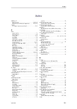
familiarization ........................ 147, 164, 285–286
installation, side view example .......... 71–72,
installation, top view example ................ 70,
lifting .............................................. 148, 165
main parts identification ............ 147, 164, 285–286
mechanical support .................... 89, 107, 152, 170
orientation................................................. 69
outline dimensions..................................... 398
power requirements.................................... 396
quality check ..................................... 155, 173
support brackets........................ 89, 107, 152, 170
unpacking ......................................... 148, 165
visual inspection ....................................... 276
weight ................................................... 398
defining athwartships location ......................... 58
defining fore and aft location........................... 57
environmental requirements.......................... 400
introduction ......................................... 26, 282
noise considerations ..................................... 58
outline dimensions drawing .................... 449, 452
overview ............................................ 26, 282
purpose .............................................. 26, 282
requirements ............................................ 399
Hydraulic Power Pack
installation .......................................... 99, 117
I
cable requirements..................................... 259
hull unit main parts .................. 147, 164, 285–286
Motor Control Unit main parts....................... 287
line socket............................................... 229
creating backup image ................................ 383
creating bootable USB flash drive ................... 386
restoring from a backup image....................... 385
before you power up..................................... 17
hoist/lower transducer manually ....................... 18
if something breaks down .............................. 18
power off .................................................. 18
reminders.................................................. 17
switch off ................................................. 18
transducer handling........................... 19, 29, 511
when not in use........................................... 18
when you are docking your vessel..................... 18
information
high voltage......................................... 43, 518
online ...................................................... 16
support .................................................... 47
Information
NMEA 0183 ...................................... 338, 404
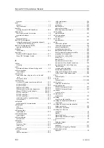
environmental inspection of the transceiver ........ 279
environmental inspection of the Transceiver
Unit..................................................... 279
hull unit installation quality check ............ 155, 173
installation trunk mounting quality
check ............................................. 126, 136
mounting flange, gate valve and transducer
dock installation ................................ 100, 118
sonar room ........................................ 155, 173
transducer ................................... 154, 172, 277
transportation boxes ................................... 500
units...................................................... 500
visual inspection of the computer.................... 270
visual inspection of the display ...................... 268
visual inspection of the hull unit..................... 276
visual inspection of the Operating Panel ........... 271
visual inspection of the Power Supply Unit ........ 274
visual inspection of the Processor Unit ............. 270
visual inspection of the transceiver.................. 272
visual inspection of the Transceiver Unit........... 272
computer ................................................ 178
display ................................................... 177
drawings................................................... 15
Enix ...................................................... 178
instructions ............................................... 15
overview .................................................. 51
Power Supply Unit .................................... 183
Processor Unit.......................................... 178
requirements for installation personnel ............... 55
summary .................................................. 51
tasks ....................................................... 51
Transceiver Unit ....................................... 184
general requirements .................................... 46
installation drawing
gate valve ................................... 471, 473, 475
mounting flange ............................ 471, 473, 475
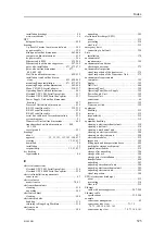
about ..................................................... 437
approval ................ 15, 53, 123, 133, 143, 160, 437
creating ......................................... 15, 53, 437
download.................................................. 54
prerequisites ............................................ 198
installation trunk
blind panel outline dimensions................. 463–464
installing ventilation pipe for air bleeding.......... 169
outline dimensions drawing .............. 455, 458, 460
quality check ..................................... 126, 136
scope of supply........................................... 35
installing
gate valve ........................................... 96, 113
Gate Valve Control Unit .......................... 99, 117
Hydraulic Power Pack............................. 99, 117
mounting flange .................................... 90, 108
Operating Panel ........................................ 180
Operating Panel Power Supply ...................... 182
transducer dock .................................... 97, 115
installation ................................................ 15
unpacking ............................................... 502
sonar room ................................................ 66
sonar room ................................................ 67
list ........................................................ 195
motion reference unit (MRU) setup ................. 333
setting up GPS interface .............................. 328
Simrad SC90 Installation Manual
Содержание SC90
Страница 2: ......
Страница 16: ...14 419050 B Simrad SC90 ...
Страница 219: ...419050 B 217 Øverland UPC 3005 Dimensions Cable layout and interconnections ...
Страница 223: ...419050 B 221 Øverland UPC 5000P Dimensions Cable layout and interconnections ...
Страница 364: ...362 419050 B Requirements Results A noise speed curve is created Date and signature Simrad SC90 Installation Manual ...
Страница 438: ...436 419050 B 427177 Transducer dock dimensions page 494 Simrad SC90 Installation Manual ...
Страница 441: ...419050 B 439 Drawing file ...
Страница 442: ...440 419050 B Simrad SC90 Installation Manual ...
Страница 445: ...419050 B 443 Drawing file ...
Страница 451: ...419050 B 449 413125 Hull Unit dimensions SC90 Download the source drawing from https www simrad com sc90 Drawing file ...
Страница 452: ...450 419050 B Simrad SC90 Installation Manual ...
Страница 455: ...419050 B 453 Drawing file ...
Страница 458: ...456 419050 B Simrad SC90 Installation Manual ...
Страница 463: ...419050 B 461 Drawing file ...
Страница 468: ...466 419050 B Simrad SC90 Installation Manual ...
Страница 469: ...419050 B 467 Related topics Installing the optional gate valve DN350 page 84 Drawing file ...
Страница 471: ...419050 B 469 Drawing file ...
Страница 472: ...470 419050 B Related topics Installing the optional gate valve DN500 page 103 Simrad SC90 Installation Manual ...
Страница 473: ...419050 B 471 214043 Gate valve installation DN350 Drawing file ...
Страница 474: ...472 419050 B Related topics Installing the optional gate valve DN350 page 84 Simrad SC90 Installation Manual ...
Страница 475: ...419050 B 473 422915 Gate valve installation DN350 Drawing file ...
Страница 476: ...474 419050 B Related topics Installing the optional gate valve DN350 page 84 Simrad SC90 Installation Manual ...
Страница 477: ...419050 B 475 083045 Gate valve installation DN500 Drawing file ...
Страница 478: ...476 419050 B Related topics Installing the optional gate valve DN500 page 103 Simrad SC90 Installation Manual ...
Страница 479: ...419050 B 477 33414 Gate valve dimensions DN350 Drawing file ...
Страница 480: ...478 419050 B Simrad SC90 Installation Manual ...
Страница 481: ...419050 B 479 Related topics Installing the optional gate valve DN350 page 84 Drawing file ...
Страница 482: ...480 419050 B 33473 Gate valve dimensions DN350 Simrad SC90 Installation Manual ...
Страница 483: ...419050 B 481 Related topics Installing the optional gate valve DN350 page 84 Drawing file ...
Страница 484: ...482 419050 B 33498 Gate valve dimensions DN500 Simrad SC90 Installation Manual ...
Страница 485: ...419050 B 483 Drawing file ...
Страница 486: ...484 419050 B Related topics Installing the optional gate valve DN500 page 103 Simrad SC90 Installation Manual ...
Страница 487: ...419050 B 485 37357 Gate valve dimensions DN500 Drawing file ...
Страница 488: ...486 419050 B Simrad SC90 Installation Manual ...
Страница 489: ...419050 B 487 Related topics Installing the optional gate valve DN500 page 103 Drawing file ...
Страница 491: ...419050 B 489 Drawing file ...
Страница 493: ...419050 B 491 430192 Transducer dock dimensions Download the source drawing from https www simrad com sc90 Drawing file ...
Страница 494: ...492 419050 B Simrad SC90 Installation Manual ...
Страница 495: ...419050 B 493 Related topics Installing the optional gate valve DN350 page 84 Drawing file ...
Страница 497: ...419050 B 495 Drawing file ...
Страница 498: ...496 419050 B Related topics Installing the optional gate valve DN500 page 103 Simrad SC90 Installation Manual ...
Страница 542: ... 2018Kongsberg Maritime ISBN xxx ...
Страница 543: ......
Страница 544: ...Simrad SC90 Fish finding sonar Installation Manual ...


