419050/B
99
7
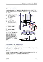
Lower the transducer dock carefully onto the gate valve while tightening the nuts.
8
Disconnect and remove the tackles from the transducer dock.
9
Tighten the nuts to torque 472 Nm.
10
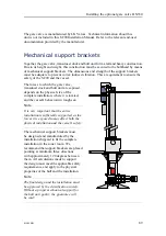
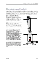
Depending on mechanical support provided by the existing decks and/or bulkheads,
design, manufacture an install additional mechanical support for the transducer
dock.
The necessity of such mechanical support must be decided by a naval architect.
Installing the hydraulic units
If a hydraulic system has been chosen to control the gate valve operation, additional
units must be installed.
Prerequisites
You must be equipped with a standard set of tools. This tool set must comprise the
normal tools for mechanical tasks. This includes different screwdriver types, pliers,
adjustable spanners etc. Each tool must be provided in various sizes. We recommend
that all tools are demagnetized to protect your equipment. Depending on the tasks at
hand, additional tools may be required.
Context
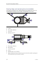
On a manually operated gate valve, a wheel is used to open and close the valve. The
wheel is fitted on gate valve, which means that you need to go down to the bottom of the
vessel to operate it. On a hydraulic operated gate valve, the control wheel is replaced
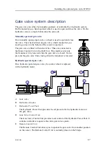
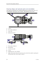
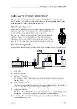
with a hydraulic motor. The hydraulic system comprises the following units:
• Hydraulic Power Pack
The Hydraulic Power Pack provides the oil pressure for the hydraulic motor on the
gate valve.
• Gate Valve Control Unit
The Gate Valve Control Unit provides local control of the Hydraulic Power Pack. It
contains controllers to operate the entire gate valve system.
• Remote Control Unit (Optional)
The Remote Control Unit allows you to operate the gate valve from another position
on the vessel. The Remote Control Unit is normally placed on the bridge.
A control cable connects the hydraulic gate valve and the Gate Valve Control Unit to
the Motor Control Unit.
The gate valve and the hydraulic units are manufactured by LK Valves. Refer to the
relevant end-user documentation provided by the manufacturer.
Содержание SC90
Страница 2: ......
Страница 16: ...14 419050 B Simrad SC90 ...
Страница 219: ...419050 B 217 Øverland UPC 3005 Dimensions Cable layout and interconnections ...
Страница 223: ...419050 B 221 Øverland UPC 5000P Dimensions Cable layout and interconnections ...
Страница 364: ...362 419050 B Requirements Results A noise speed curve is created Date and signature Simrad SC90 Installation Manual ...
Страница 438: ...436 419050 B 427177 Transducer dock dimensions page 494 Simrad SC90 Installation Manual ...
Страница 441: ...419050 B 439 Drawing file ...
Страница 442: ...440 419050 B Simrad SC90 Installation Manual ...
Страница 445: ...419050 B 443 Drawing file ...
Страница 451: ...419050 B 449 413125 Hull Unit dimensions SC90 Download the source drawing from https www simrad com sc90 Drawing file ...
Страница 452: ...450 419050 B Simrad SC90 Installation Manual ...
Страница 455: ...419050 B 453 Drawing file ...
Страница 458: ...456 419050 B Simrad SC90 Installation Manual ...
Страница 463: ...419050 B 461 Drawing file ...
Страница 468: ...466 419050 B Simrad SC90 Installation Manual ...
Страница 469: ...419050 B 467 Related topics Installing the optional gate valve DN350 page 84 Drawing file ...
Страница 471: ...419050 B 469 Drawing file ...
Страница 472: ...470 419050 B Related topics Installing the optional gate valve DN500 page 103 Simrad SC90 Installation Manual ...
Страница 473: ...419050 B 471 214043 Gate valve installation DN350 Drawing file ...
Страница 474: ...472 419050 B Related topics Installing the optional gate valve DN350 page 84 Simrad SC90 Installation Manual ...
Страница 475: ...419050 B 473 422915 Gate valve installation DN350 Drawing file ...
Страница 476: ...474 419050 B Related topics Installing the optional gate valve DN350 page 84 Simrad SC90 Installation Manual ...
Страница 477: ...419050 B 475 083045 Gate valve installation DN500 Drawing file ...
Страница 478: ...476 419050 B Related topics Installing the optional gate valve DN500 page 103 Simrad SC90 Installation Manual ...
Страница 479: ...419050 B 477 33414 Gate valve dimensions DN350 Drawing file ...
Страница 480: ...478 419050 B Simrad SC90 Installation Manual ...
Страница 481: ...419050 B 479 Related topics Installing the optional gate valve DN350 page 84 Drawing file ...
Страница 482: ...480 419050 B 33473 Gate valve dimensions DN350 Simrad SC90 Installation Manual ...
Страница 483: ...419050 B 481 Related topics Installing the optional gate valve DN350 page 84 Drawing file ...
Страница 484: ...482 419050 B 33498 Gate valve dimensions DN500 Simrad SC90 Installation Manual ...
Страница 485: ...419050 B 483 Drawing file ...
Страница 486: ...484 419050 B Related topics Installing the optional gate valve DN500 page 103 Simrad SC90 Installation Manual ...
Страница 487: ...419050 B 485 37357 Gate valve dimensions DN500 Drawing file ...
Страница 488: ...486 419050 B Simrad SC90 Installation Manual ...
Страница 489: ...419050 B 487 Related topics Installing the optional gate valve DN500 page 103 Drawing file ...
Страница 491: ...419050 B 489 Drawing file ...
Страница 493: ...419050 B 491 430192 Transducer dock dimensions Download the source drawing from https www simrad com sc90 Drawing file ...
Страница 494: ...492 419050 B Simrad SC90 Installation Manual ...
Страница 495: ...419050 B 493 Related topics Installing the optional gate valve DN350 page 84 Drawing file ...
Страница 497: ...419050 B 495 Drawing file ...
Страница 498: ...496 419050 B Related topics Installing the optional gate valve DN500 page 103 Simrad SC90 Installation Manual ...
Страница 542: ... 2018Kongsberg Maritime ISBN xxx ...
Страница 543: ......
Страница 544: ...Simrad SC90 Fish finding sonar Installation Manual ...

