419050/B
225
"Event" message. The message is processed by the SC90 software, and it will (if the
previous ping has been finished) start the ping sequence.
As an acknowledge to the synchronisation trigger, the SC90 sets the Ready To Send
(RTS) signal to a logic "low" before transmitting. This indicates that the SC90 is "busy".
Once the transmission and reception sequence ends, the SC90 sets the Ready To Send
(RTS) signal to logic "high" to indicate that it is ready for the next ping.
Master
mode
When the SC90 is "Master" in a system, the synchronization can either take place in
Free
running
mode, or in
Wait for slave
mode.
• Synchronization in
Free running
mode
When in
Free running
mode, the SC90 will ping as fast as possible, setting its Ready
to Send (RTS) signal to a logic "high" at start of each ping, and back to logic "low”
at the end of the ping. The "Slave" system is triggered the when the Ready to Send
(RTS) signal goes from "low" to "high".
• Synchronization in
Wait for slave
mode
When in
Wait for slave
mode, the SC90 will wait for a logic "high" Clear to Send
(CTS) signal from the "Slave" system before it starts a new ping sequence. This is the
"ready to ping" acknowledge from the "Slave" system.
Note
If you use the SC90 as "Master" to control two "Slave" systems, you must connect a
single cable (plus ground) from the Ready to Send (RTS) output on the Master system to
the Clear to Send (CTS) input on both "Slave" systems. The return from the Ready to
Send (RTS) outputs on the "Slave" systems can not be connected.
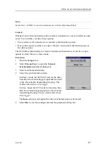
Selecting synchronization port
If you wish to use the SC90 as a master or slave in a synchronized system, you must set
it up for such operation. To do this, you must select which communication port to use for
the synchronization interface, and you must select the requested synchronization mode.
Prerequisites
Neither tools nor instruments are required. The SC90 is turned on, and it is working
normally.
• For "slave" operation, a remote system (for example
K-Sync
) must be available to
provide trigger pulses.
• For "master" operation, a remote system must be connected. This remote system
must be set up in "slave" mode.
The external system is connected to a serial communication port on the Processor Unit.
Содержание SC90
Страница 2: ......
Страница 16: ...14 419050 B Simrad SC90 ...
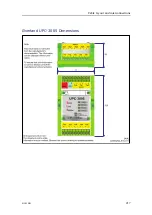
Страница 219: ...419050 B 217 Øverland UPC 3005 Dimensions Cable layout and interconnections ...
Страница 223: ...419050 B 221 Øverland UPC 5000P Dimensions Cable layout and interconnections ...
Страница 364: ...362 419050 B Requirements Results A noise speed curve is created Date and signature Simrad SC90 Installation Manual ...
Страница 438: ...436 419050 B 427177 Transducer dock dimensions page 494 Simrad SC90 Installation Manual ...
Страница 441: ...419050 B 439 Drawing file ...
Страница 442: ...440 419050 B Simrad SC90 Installation Manual ...
Страница 445: ...419050 B 443 Drawing file ...
Страница 451: ...419050 B 449 413125 Hull Unit dimensions SC90 Download the source drawing from https www simrad com sc90 Drawing file ...
Страница 452: ...450 419050 B Simrad SC90 Installation Manual ...
Страница 455: ...419050 B 453 Drawing file ...
Страница 458: ...456 419050 B Simrad SC90 Installation Manual ...
Страница 463: ...419050 B 461 Drawing file ...
Страница 468: ...466 419050 B Simrad SC90 Installation Manual ...
Страница 469: ...419050 B 467 Related topics Installing the optional gate valve DN350 page 84 Drawing file ...
Страница 471: ...419050 B 469 Drawing file ...
Страница 472: ...470 419050 B Related topics Installing the optional gate valve DN500 page 103 Simrad SC90 Installation Manual ...
Страница 473: ...419050 B 471 214043 Gate valve installation DN350 Drawing file ...
Страница 474: ...472 419050 B Related topics Installing the optional gate valve DN350 page 84 Simrad SC90 Installation Manual ...
Страница 475: ...419050 B 473 422915 Gate valve installation DN350 Drawing file ...
Страница 476: ...474 419050 B Related topics Installing the optional gate valve DN350 page 84 Simrad SC90 Installation Manual ...
Страница 477: ...419050 B 475 083045 Gate valve installation DN500 Drawing file ...
Страница 478: ...476 419050 B Related topics Installing the optional gate valve DN500 page 103 Simrad SC90 Installation Manual ...
Страница 479: ...419050 B 477 33414 Gate valve dimensions DN350 Drawing file ...
Страница 480: ...478 419050 B Simrad SC90 Installation Manual ...
Страница 481: ...419050 B 479 Related topics Installing the optional gate valve DN350 page 84 Drawing file ...
Страница 482: ...480 419050 B 33473 Gate valve dimensions DN350 Simrad SC90 Installation Manual ...
Страница 483: ...419050 B 481 Related topics Installing the optional gate valve DN350 page 84 Drawing file ...
Страница 484: ...482 419050 B 33498 Gate valve dimensions DN500 Simrad SC90 Installation Manual ...
Страница 485: ...419050 B 483 Drawing file ...
Страница 486: ...484 419050 B Related topics Installing the optional gate valve DN500 page 103 Simrad SC90 Installation Manual ...
Страница 487: ...419050 B 485 37357 Gate valve dimensions DN500 Drawing file ...
Страница 488: ...486 419050 B Simrad SC90 Installation Manual ...
Страница 489: ...419050 B 487 Related topics Installing the optional gate valve DN500 page 103 Drawing file ...
Страница 491: ...419050 B 489 Drawing file ...
Страница 493: ...419050 B 491 430192 Transducer dock dimensions Download the source drawing from https www simrad com sc90 Drawing file ...
Страница 494: ...492 419050 B Simrad SC90 Installation Manual ...
Страница 495: ...419050 B 493 Related topics Installing the optional gate valve DN350 page 84 Drawing file ...
Страница 497: ...419050 B 495 Drawing file ...
Страница 498: ...496 419050 B Related topics Installing the optional gate valve DN500 page 103 Simrad SC90 Installation Manual ...
Страница 542: ... 2018Kongsberg Maritime ISBN xxx ...
Страница 543: ......
Страница 544: ...Simrad SC90 Fish finding sonar Installation Manual ...


