342
419050/B
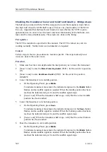
Checking the transducer lower and hoist functionality - Bridge steps
The hull unit provided with the SC90 is designed to lower the transducer down below
the ship’s hull when the SC90 shall be used. This is a key functionality of the SC90.
It is very important that the hoist/lower function is tested before the SC90 is put to
operational use. In order to test the lower and hoist functionality of the hull unit, two
tasks must be done simultaneously. These tasks are done on the bridge.
Prerequisites
The SC90 is installed as specified in this manual. The SC90 is turned on, and it is
working normally. Neither tools nor instruments are required.
Context
Certain steps in the two procedures are location specific. The steps marked [
Sonar
room
] are done in the sonar room.
Procedure
1
Make sure that the water depth under the keel permits you to lower the transducer.
2
[
Sonar room
] Locate the
Motor Protecting Switch
(S301). Set the switch to position
ON
.
3
[
Sonar room
] Locate
Hoist/Lower Switch
(S302). Set the switch to position
REMOTE
.
4
Lower the transducer to its middle position.
a
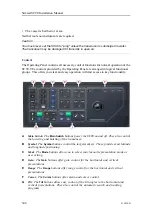
On the Operating Panel, press
Middle
.
To indicate transducer movement, the indicator lamp next to the
Middle
button
flashes, and an audible signal is sounded. When the middle position has been
reached, the indicator lamp is lit, and the audible signal stops.
b
[
Sonar room
] When the transducer shaft stops, verify that the correct middle
position has been reached.
5
Lower the transducer to its bottom position.
a
On the Operating Panel, press
Down
.
To indicate transducer movement, the indicator lamp next to the
Down
button
flashes, and an audible signal is sounded. When the bottom position has been
reached, the indicator lamp is lit, and the audible signal stops.
b
[
Sonar room
] When the transducer shaft stops, verify that the correct bottom
position has been reached.
6
Hoist the transducer to its middle position.
a
On the Operating Panel, press
Middle
.
To indicate transducer movement, the indicator lamp next to the
Middle
button
flashes, and an audible signal is sounded. When the middle position has been
reached, the indicator lamp is lit, and the audible signal stops.
Simrad SC90 Installation Manual
Содержание SC90
Страница 2: ......
Страница 16: ...14 419050 B Simrad SC90 ...
Страница 219: ...419050 B 217 Øverland UPC 3005 Dimensions Cable layout and interconnections ...
Страница 223: ...419050 B 221 Øverland UPC 5000P Dimensions Cable layout and interconnections ...
Страница 364: ...362 419050 B Requirements Results A noise speed curve is created Date and signature Simrad SC90 Installation Manual ...
Страница 438: ...436 419050 B 427177 Transducer dock dimensions page 494 Simrad SC90 Installation Manual ...
Страница 441: ...419050 B 439 Drawing file ...
Страница 442: ...440 419050 B Simrad SC90 Installation Manual ...
Страница 445: ...419050 B 443 Drawing file ...
Страница 451: ...419050 B 449 413125 Hull Unit dimensions SC90 Download the source drawing from https www simrad com sc90 Drawing file ...
Страница 452: ...450 419050 B Simrad SC90 Installation Manual ...
Страница 455: ...419050 B 453 Drawing file ...
Страница 458: ...456 419050 B Simrad SC90 Installation Manual ...
Страница 463: ...419050 B 461 Drawing file ...
Страница 468: ...466 419050 B Simrad SC90 Installation Manual ...
Страница 469: ...419050 B 467 Related topics Installing the optional gate valve DN350 page 84 Drawing file ...
Страница 471: ...419050 B 469 Drawing file ...
Страница 472: ...470 419050 B Related topics Installing the optional gate valve DN500 page 103 Simrad SC90 Installation Manual ...
Страница 473: ...419050 B 471 214043 Gate valve installation DN350 Drawing file ...
Страница 474: ...472 419050 B Related topics Installing the optional gate valve DN350 page 84 Simrad SC90 Installation Manual ...
Страница 475: ...419050 B 473 422915 Gate valve installation DN350 Drawing file ...
Страница 476: ...474 419050 B Related topics Installing the optional gate valve DN350 page 84 Simrad SC90 Installation Manual ...
Страница 477: ...419050 B 475 083045 Gate valve installation DN500 Drawing file ...
Страница 478: ...476 419050 B Related topics Installing the optional gate valve DN500 page 103 Simrad SC90 Installation Manual ...
Страница 479: ...419050 B 477 33414 Gate valve dimensions DN350 Drawing file ...
Страница 480: ...478 419050 B Simrad SC90 Installation Manual ...
Страница 481: ...419050 B 479 Related topics Installing the optional gate valve DN350 page 84 Drawing file ...
Страница 482: ...480 419050 B 33473 Gate valve dimensions DN350 Simrad SC90 Installation Manual ...
Страница 483: ...419050 B 481 Related topics Installing the optional gate valve DN350 page 84 Drawing file ...
Страница 484: ...482 419050 B 33498 Gate valve dimensions DN500 Simrad SC90 Installation Manual ...
Страница 485: ...419050 B 483 Drawing file ...
Страница 486: ...484 419050 B Related topics Installing the optional gate valve DN500 page 103 Simrad SC90 Installation Manual ...
Страница 487: ...419050 B 485 37357 Gate valve dimensions DN500 Drawing file ...
Страница 488: ...486 419050 B Simrad SC90 Installation Manual ...
Страница 489: ...419050 B 487 Related topics Installing the optional gate valve DN500 page 103 Drawing file ...
Страница 491: ...419050 B 489 Drawing file ...
Страница 493: ...419050 B 491 430192 Transducer dock dimensions Download the source drawing from https www simrad com sc90 Drawing file ...
Страница 494: ...492 419050 B Simrad SC90 Installation Manual ...
Страница 495: ...419050 B 493 Related topics Installing the optional gate valve DN350 page 84 Drawing file ...
Страница 497: ...419050 B 495 Drawing file ...
Страница 498: ...496 419050 B Related topics Installing the optional gate valve DN500 page 103 Simrad SC90 Installation Manual ...
Страница 542: ... 2018Kongsberg Maritime ISBN xxx ...
Страница 543: ......
Страница 544: ...Simrad SC90 Fish finding sonar Installation Manual ...

