Installation Instructions Document No. 466-1574
.
10
Planning Control Locations
Control Panel
Locate the Control Panel so that the alarm sounds can
be heard and the Control Panel will be convenient to
operate. It must be near an electrical outlet and tele-
phone receptacle.
Remote Handheld Touchpad and Touchtalk 2-
Way RF Touchpad*
Locate Remote Handheld Touchpads and the wall-
mounted Touchtalk 2-Way RF Touchpad where they
will be convenient and offer quick access to the user.
KeyChain Touchpad
KeyChain Touchpads attach to the owner’s key ring
or can be conveniently carried.
Planning for Lamp*, Appliance*,
Wallswitch*, and Universal/Garage
Door* Module Control
As you program the modules, the Control Panel asks
you to choose the house code, unit number and acti-
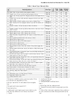
vation method. Fill out Table 6 on page 9, Home Con-
trol Planning Table, before you begin programming.
The system can control 8 individual unit numbers on
Lamp, Wallswitch, Appliance, and Universal/Garage
Door Modules.
Setting the House Code and Unit Num-
ber
Each device (lamp, appliance, garage door, etc.) con-
trolled by the Control Panel must have an identifica-
tion setting. The modules use two dials to set
identification codes: one with letters A through P and
one with numbers 1 through 16.
The lettered dial sets the house code. The house code
enables the system to differentiate this home from
other homes in the area. Set all modules (except the
remote siren) and the Control Panel to the same house
code.
The numbered dial sets the unit number. The unit
number tells the system which device you want to
control. Each unit number should be different (unless
you want specific lights or appliances to be activated
together). The Control Panel recognizes up to 8 unit
numbers for sensor-activated, time-activated and en-
try/exit delay lights. When unit numbers 9-16 are
used for lamp modules, they can only be controlled by
an all on or all off command.
A lamp will flash to the arming level if its unit number
is set to 10. A lamp set to unit number 10 will flash
once if the Control Panel is disarmed, twice if doors
& windows are armed, etc.
The remote siren can be set to any unit number to hear
alarm sounds. Set it to unit number 9 to also hear arm-
ing level beeps, status beeps, and trouble beeps.
To Fill Out the Home Control Planning Table:
Note: Do not use a lamp module to control appliances, use
an appliance module, since the wattage rating on Lamp
Modules is less than on Appliance Modules.
1. Set the house code on all the Modules, except the
remote siren to the same letter.
Note: The house code instructions which come with the
Powerhorn Siren won’t work with this Control Panel. Follow
the house-code instructions given here.
Set the Remote Siren house code to the next al-
phabetical letter. For example, if the house code
is B, set the remote siren’s house code to C.
2. Set the Module unit numbers.
Note: If you are using a Universal Module to operate a ga-
rage door, make sure to assign a unique unit number to this
Module choosing from 1-8.
3. List the location of the lamp or appliance in the
Location column of Table 6 on page 9.
4. Write the location of each Lamp Module on an
adhesive note and label the module.
5. Decide if the device should be activated by sen-
sors, entry/exit delay, time, or a combination. An
example of sensor activation is using a motion
sensor to turn on a light. Record the information
in the appropriate columns.
* = Not Available with Basic Model


