background image

Installation Instructions Document No. 466-1574

40 

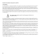
Canada Notice

The Canadian Department of Communications label identifies certified equipment. This certification means that the equipment meets certain telecommunica-
tions network protective, operational, and safety requirements. The department does not guarantee the equipment will operate to the user’s satisfaction.

Before installing this equipment, users should ensure that it is permissible to be connected to the facilities of the local telecommunications company. The 
equipment must also be installed using an acceptable method of connection. In some cases, the company’s inside wiring associated with a single-line individ-
ual service may be extended by means of a certified connector assembly (telephone extension cord). The customer should be aware that compliance with the 
above conditions may not prevent degradation of service in some situations.

Repairs to certified equipment should be made by an authorized Canadian maintenance facility designated by the supplier. Any repairs or alterations made by 
the user to this equipment, or equipment malfunctions, may give the telecommunications company cause to request the user to disconnect the equipment.

For your protection, make sure that the electrical ground connections of the power utility, telephone lines, and internal metallic water pipe system, if present, 
are connected together

The Load Number (LN) assigned to each terminal device denotes the percentage of the total load to be connected to a telephone loop which is used by the 
device, to prevent overloading. The termination on a loop may consist of any combination of devices subject only to the requirement that the total of the LNs 
of all the devices does not exceed 100. Load Number: .1 The term “IC:” before the certification/registration number only signifies that the Industry Canada 
technical specifications were met.
 IC: 867A 787SIMON

“AVIS: - L ´étiquette du ministère des Communications du Canada identifie le matériel homologué. Cette étiquette certifie que le matériel est conforme a cer-
taines normes de protection, d ´ exploitation et de sécurité des réseaux de télécommunications. Le ministère n ´ assure toutefois pas que le matériel fonction-
nera a la satisfaction de l ´ utilisateur.

Avant d ´ installer ce matériel, l ´ utilisateur doit s ´ assurer qu´ il est permis de le raccorder aux installations de l ´ enterprise locale de télécommunication. Le 
matériel doit également etre installé en suivant une méthod acceptée de raccordement. Dans certains cas, les fils intérieurs de l´ enterprise utilisés pour un ser-
vice individuel a ligne unique peuvent etre prolongés au moyen d´ un dispositif homologué de raccordement (cordon prolongateur téléphonique interne). L ´ 
abonné ne doit pas oublier qu ´ il est possible que la conformité aux conditions énoncées ci-dessus n ´ empechent pas le dégradation du service dans certaines 
situations. Actuellement, les enterprises de télécommunication ne permettent pas que l ´ on raccorde leur matériel a des jacks d ´ abonné, sauf dans les cas pré-
cis prévus pas les tarrifs particuliers de ces enterprises.

Les réparations de matériel homologué doivent etre effectuées pas un centre d ´ entretien canadien autorisé désigné par le fournisseur. La compagne de télé-
communications peut demander a l ´ utilisateur de débrancher un appareil a la suite de réparations ou de modifications effectuées par l ´ utilisateur ou a cause 
de mauvais fonctionnement.

Pour sa propre protection, l ´ utilisateur doit s ´ assurer que tous les fils de mise a la terre de la source d ´ énergie électrique, des lignes téléphoniques et des 
canalisations d ´´ eau métalliques, s ´ il y en a, sont raccordés ensemble. Cette précaution est particulièrement importante dans les régions rurales.

Avertissment. - L ´ utilisateur ne doit pas tenter de faire ces raccordements lui-meme; il doit avoir recours a un service d ´ inspection des installations élec-
triques, ou a electricien, selon le cas”.

Une note explicative sur les indices de charge (voir 1.6) et leur emploi, a l ´ intention des utilisateurs du matériel terminal, doit etre incluse dans l ´ information 
qui accompagne le materiel homologué. La note pourrait etre rédigée selon le modèle suivant:

“L ´ indice de charge (IC) assigné a chaque dispositif terminal indique, pour éviter toute surcharge, le pourcentage de la charge totale qui peut etre raccordée a 
un circuit téléphonique bouclé utilisé par ce dispositif. La terminaison du circuit bouclé peut etre constituée de n ´ import somme des indices de charge de l ´ 
ensemble des dispositifs ne dépasse pas 100.”

L ´ Indice de charge de cet produit est ____________.

Do not attempt to make connections yourself. Contact the appropriate electrician or elec-
tric inspections authroity.

Caution

!

Содержание Basic ITI 60-776-02-95R

Страница 1: ...Rechargeable Battery 25 Connecting the Phone Line to the Control Panel 25 Installing an RJ 31X Jack 25 Connecting the Phone Line to the Control Panel 25 Programming Overview 26 Programming Sensors 27...

Страница 2: ...n 46 Fire Shutdown AVM Option 47 AVM Mode Option 48 Panic Talk Modules that Cannot be Used with Simon Basic Interrogator 200 Audio Verification Module AVM 60 787 X 10 Lamp 13 403 Appliance 13 402 Powe...

Страница 3: ...Power Transformer 22 091 9 Volt 1 2 Ah Lithium Backup Battery 34 037 or a rechargeable 7 2Volt 1 Ah Nickel Metal Hydride Battery Pack 34 052 Hardwire Siren 13 046 or LD105 Siren 13 374 Residential Bu...

Страница 4: ...owerhorn Remote Siren Modules 13 398 X 10 Universal Garage Door Modules 13 399 X 10 Wall Switch Modules 13 397 Note Use of the above X 10 modules has not been inves tigated by UL Figure 1 shows the Co...

Страница 5: ...o install Door Window sensors on every opening Identify areas where an intruder is likely to walk Large areas in an open floor plan downstairs family rooms and hallways are candidates for Indoor Motio...

Страница 6: ...system panel allowing the HomeLink to control the arming disarming and light functions of the security system The IHT also en ables the user to control the garage door opener from the HomeLink The IT...

Страница 7: ...or type is instant intrusion it does not require restoral or supervisory communication with the Control Panel and it is active in 4 arming levels disarm arm doors windows arm motion sensors and arm do...

Страница 8: ...or Type Remote Locations Front Door Back Door Garage Door Bedroom Guest Room Child s Room Utility Room Living Room Dining Room Bathroom Laundry Room Kitchen Office Den Garage Special Chime Basement Up...

Страница 9: ...ion I Yes Yes 1234 09 Special Intrusion such as gun cabinets and wall safes Intrusion S Yes Yes 1234 10 Entry Exit Delay Entry Exit Delay that require a standard delay time Chime Intrusion S Yes Yes 2...

Страница 10: ...ss you want specific lights or appliances to be activated together The Control Panel recognizes up to 8 unit numbers for sensor activated time activated and en try exit delay lights When unit numbers...

Страница 11: ...eyChain Touchpad activates the universal module to open the garage door or to turn on special lights if programmed 9 16 Used for lamp modules and controlled by an all on or all off command 9 Used for...

Страница 12: ...ould be used by children a baby sitter or a service person These codes cannot be used for programming Panic Code The Panic Code is able to disarm or subdisarm the panel and send a silent alarm to the...

Страница 13: ...work Silent alarms report to a pager as an intrusion alarm See Table 17 on page 17 for more reporting information Option 06 Downloader Phone Number Programs the ITI ToolBox Downloader telephone number...

Страница 14: ...will hear 2 beeps if arming to level 2 The panel will sound three sets of warning beeps if a sen sor that requires restoral is open during the exit delay if auto arm is off option 38 The panel will pr...

Страница 15: ...ler delay expires and opening reports are on Both the alarm and opening report will be called in immedi ately Option 18 Alarm Cancel Add enables alarm cancel Program the time in min utes If the Contro...

Страница 16: ...the Control Panel and let the phone ring twice then hang up 2 Wait 10 40 seconds and call the Control Panel again 3 The Control Panel should answer on the first ring Program 2 Repeat steps 1 2 before...

Страница 17: ...Press 1 or 0 to speak and 3 or 6 to listen 4 Press 99 to terminate the session Note To conduct an audio session using remote phone ac cess see Table 13 on page 14 Option 34 Fail to Open Add enables f...

Страница 18: ...e trouble beeps will stop and then resume 4 hours later Trouble beeps will be heard if There is AC power failure The CPU battery is low There is a sensor failure There is sensor trouble There is a fai...

Страница 19: ...Delete disables AVM mode When this option is off the two way session will start immediately Option 48 Panic Talk Add enables panic talk This allows the central station to listen and talk to the user d...

Страница 20: ...g a hardwire siren and supervision is desired See the Wiring the Control Panel on page 21 for the correct EOL resistor connection Delete turns hardwire supervision off and is the ap propriate setting...

Страница 21: ...U2 11 Exit Delay 030 sec 005 sec 005 120 sec U1 U2 12 Phone Mod 1 0 0 0 3 U1 13 Phone Mod 2 0 0 0 9 U1 14 DTMF On Pulse On Off U1 U2 15 No Activity Report Off Off 02 24 hrs U1 U2 16 Auto Phone Test M...

Страница 22: ...in Siren never times out 01 30 min utes U1 U2 40 Trouble Beeps On Off On Off U1 U2 41 Chime Voice Off Off On Off U1 U2 M 42 Speaker Level On Low On Off U1 U2 M 43 Pager Phone Number Off Off 22 digits...

Страница 23: ...siren supervision When option 53 is on and a hardwire interior siren is not connected a 47k ohm resistor two 47k ohm resistors are shipped with the Control Panel must be connected across the positive...

Страница 24: ...gure 5 Power Transformer Control Panel Con nections Connecting the Backup Batteries Installing a Non rechargeable Battery Connect a 9 Volt lithium battery ITI 34 037 to the battery strap as shown in F...

Страница 25: ...ll be monitored by a central monitor ing station you must install an RJ 31X jack between the telephone company TELCO block and the Con trol Panel The jack must be located within 5 feet of the Control...

Страница 26: ...tand the flow from left to right when using the programming buttons Follow the programming arrows or use the flow dia grams to the right of the programming buttons The Control Panel will voice prompt...

Страница 27: ...uest room child s room utility room liv ing room dining room bathroom laundry room kitchen office den garage special chime base ment upstairs downstairs hallway medicine cabinet closet attic Each name...

Страница 28: ...y exit delay to be operated by a sensor or at scheduled times To assign a unit number 1 See Table 6 on page 9 for your planning infor mation 2 Set the Unit number switch on each module Programming Lig...

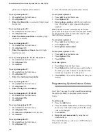
Страница 29: ...Option 03 3 Press Hours and Minutes to set the time 4 Press DONE To set system options 04 05 and 06 1 Press Add from the Start menu 2 Press Option and 04 05 or 06 3 Enter a phone number with the red n...

Страница 30: ...t menu 2 Press Option 39 3 Enter the minutes 2 digits must be entered To set system option 43 1 Press Add from the Start menu 2 Press Option 43 3 Enter a phone number with the red numbered keys Press...

Страница 31: ...ors are armed Three beeps verify that Motion Sensors are armed Four beeps verify that both Door Window and Motion sensors are armed The system cannot work without power If the electri cal power fails...

Страница 32: ...Sensors The Control Panel will arm Motion Sensors Press twice to turn Latch key on The button blinks when Latchkey is on DISARM The Control Panel will disarm Doors Windows and Motion Sensors when also...

Страница 33: ...et been tested When all sensors have been tested the Control Panel will announce Sensor test complete press DONE 7 Press DONE The system will respond Sensor Test OK 8 If Cancel or DONE is pressed and...

Страница 34: ...mini mum level avoid mounting a sensor at that loca tion 3 If the replacement sensor functions contact ITI for repair or replacement of the problem sensor Testing Phone Communication Perform a phone t...

Страница 35: ...ons on the Remote Handheld Touchpad to test individual lamp modules the Control Panel will respond with Lights on off Siren and X 10 Lamp Module Func tions All sirens will time out in the programmed s...

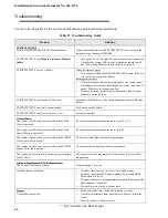
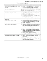
Страница 36: ...hat a sensor is open See Sensors section below SYSTEM STATUS says System time is not set Set the system time Control Panel The system says Function not available when Chime Doors is pressed No sensors...

Страница 37: ...ectly into an outlet and that the outlet is not controlled by a wall switch Possibly a bad transformer House code was programmed incorrectly One Lamp Module or Siren is not working Unplug nearby equip...

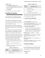
Страница 38: ...4 hours option 50 is off Table 24 Typical Backup Battery Life Cycle Over Time Months in Use Estimated Hours of Backup Power 0 30 159 1 27 861 2 25 562 3 23 264 4 20 966 5 18 668 6 16 370 7 14 072 8 1...

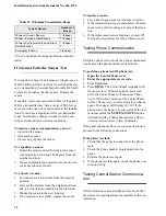
Страница 39: ...REN is separately shown on the label A plug and jack used to connect this equipment to the premises wiring and telephone network must comply with the applicable FCC Part 68 rules and require ments as...

Страница 40: ...ur Avant d installer ce mat riel l utilisateur doit s assurer qu il est permis de le raccorder aux installations de l enterprise locale de t l communication Le mat riel doit galement etre install en s...

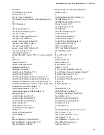
Страница 41: ...Arm 18 22 Auto Phone Test 15 21 Auxiliary Power Output 31 AVM 4 6 AVM Fire Shutdown 19 AVM Mode 19 B Backup Battery Control Panel 31 Backup Battery Connecting 24 25 Backup Battery Lithium 3 Battery P...

Страница 42: ...e 18 Motion Sensor Program Buttons 27 Motion Sensor Indoor 5 Motion Sensor Indoor Outdoor 4 Motion Sensor Outdoor 5 mount the panel 32 N No Activity 15 No Activity Report 21 No Delay from KeyChain Tou...

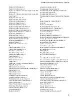
Страница 43: ...er Connecting 24 Powerhorn Siren house code 10 Primary Phone Number 13 21 Program Buttons 27 program mode 26 program the house code 28 Programming Access Codes 30 Programming Light Appliance Controls...

Страница 44: ...Numbers 16 Table Sensor Tripping Instructions 33 Table Sensor Type Characteristic 9 Table Sensor Device Location Planning 7 Table Troubleshooting Guide 36 Table Unit Number Assignments 11 Table User...

Страница 45: ...Installation Instructions Document No 466 1574 45...

Страница 46: ...Installation Instructions Document No 466 1574 46...

Страница 47: ...Installation Instructions Document No 466 1574 47...

Страница 48: ...ice Sensors Motion ARM DISARM Access Code SYSTEM STATUS Press Once Windows Doors ARM Sensors Motion ARM Press Twice Windows Doors ARM Sensors Motion ARM Windows Doors ARM Press Twice Sensors Motion AR...

Отзывы: