End Fault Protection
137
7SS52 V4 Manual
C53000-G1176-C182-3
5.4.2
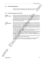
Protection with fault in the ”Dead Zone” of the Bus Coupler
Normally, the current transformer is the boundary of the protected zone (measuring
range). The zone between the current transformer and the circuit breaker is known as
the "Dead Zone". You can achieve an improved behavior of protection through detec-
tion of the circuit-breaker position when the circuit breaker is open. In this case, the
protected zone is extended by the dead zone due to device-internal measures.
With a closed circuit breaker, the protection behavior is first the same as without de-
tection of the position.
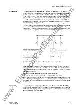
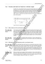
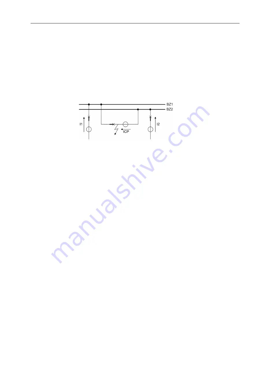
Figure 5-30 Fault in the dead zone of the bus coupler
5.4.2.1
Without detection of the circuit-breaker position
Bus coupler with
one current trans-
former
First of all, the busbar BZ1 (Figure 5-30, page 137) is switched off. The fault current is
not yet interrupted, though, since the short-circuit is still being fed from BZ2. Busbar
BZ2 must be switched off, too. For this purpose, the coupler current will be manipulat-
ed (unbalanced) device-internally after the delay time of the breaker failure protection
settable with parameter
(
XX21/CU
) has elapsed. Such unbalancing leads to
the tripping of the BZ2 busbar that is feeding the fault and, hence, to the final fault
clearing.
Bus coupler with
two current trans-
formers
If the bus coupler bay is equipped with two transformers, the two busbars BZ1 and
BZ2 will be switched off without delay, since the fault is located in the overlapping pro-
tected area of both zones.
5.4.2.2
With detection of the circuit-breaker position, circuit breaker closed
Bus coupler with
one current trans-
former
First of all, busbar BZ1 (Figure 5-30, page 137) is switched off, which does not inter-
rupt the fault current, though. The circuit breaker opens and is detected by the busbar
protection through its position indication. There, the coupler current is manipulated
(unbalanced) device-internally. Such unbalancing leads to the tripping of all of the as-
sociated circuit breakers of the BZ2 busbar and, hence, to the final fault clearing. The
detection of the circuit-breaker position leads to a reduction of the fault-clearing time
compared to Chapter 5.4.2.1, page 137.
Bus coupler with
two current trans-
formers
If the bus coupler bay is equipped with two transformers, the two busbars BZ1 and
BZ2 will be switched off without delay, since the fault is located in the overlapping pro-
tected area of both zones. The detection of the circuit-breaker position does not pro-
vide any advantage compared to Chapter 5.4.2.1, page 137.
www
. ElectricalPartManuals
. com
Содержание SIPROTEC 7SS522 V4.6
Страница 326: ...Maintenance and Repair 310 7SS52 V4 Manual C53000 G1176 C182 3 w w w E l e c t r i c a l P a r t M a n u a l s c o m ...
Страница 432: ...Appendix 416 7SS52 V4 Manual C53000 G1176 C182 3 w w w E l e c t r i c a l P a r t M a n u a l s c o m ...
Страница 438: ...Index 422 7SS52 V4 Manual C53000 G1176 C182 34 w w w E l e c t r i c a l P a r t M a n u a l s c o m ...

