12/184
Siemens Building Technologies
Basic Dokumentation RVA63.280, RVA53.280
CE1P2374E
Landis & Staefa Division
19.04.2001
2
Handling
2.1
Installation
2.1.1
Regulations for installation
.
•
Air circulation around the controller must be ensured, allowing the unit to emit the
heat produced by it.
A clearance of at least 10 mm must be provided for the controller's cooling slots
which are situated a the top and bottom of the housing.
The space should not be accessible and no objects should be placed there.
If the controller is enclosed in another closed (insulating) casing, a clearance of up to
100 mm must be observed on all sides
•
The controller is designed conforming to the directives for safety class II mounted in
compliance with these regulations
•
Power to the controller may be supplied only after it is completely fitted in the cut-out.
If this is not observed, there is a risk of electric shock hazard near the terminals and
through the cooling slots
•
The controller may not be exposed to dripping water
•
Permissible ambient temperature when mounted and when ready to
operate: 0...50 °C
2.1.2
Mounting location
•
In the boiler front
•
In the control panel front
2.1.3
Mounting procedure
•
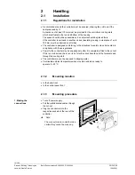
Turn off power supply
•
Pull the prefabricated cables through
the cut-out
•
Plug the connectors into the
respective sockets at the rear of the
controller
è
Note:
The connectors are coded to make
certain they cannot be mixed up.
2373Z
05
1. Making the
connections


