28/184
Siemens Building Technologies
Basic Dokumentation RVA63.280, RVA53.280
CE1P2374E
Landis & Staefa Division
19.04.2001
RVA
6
3
.2
8
0
RVA
5
3
.2
8
0
Func
ti
o
n
Ra
n
g
e
Un
it
Res
o
lu
ti
o
n
F
a
ct
o
ry
set
ti
ng
150
150
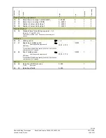
Winter- / summertime changeover
01.01...31.12
tt.MM
1
25.03
151
151
Summer- / wintertime changeover
01.01...31.12
tt.MM
1
25.10
155
155
Display of PPS communication (A6)
0 0 0
Short-circuit
- - -
No communication
0...255
OK communication
0 0 0 / - - - / 0...255
-
1
-
156
156
Display of PPS communication room unit 2 (A7)
000
Short-circuit
- - -
No communication, no room unit
0...255
Room unit number, communication OK
0...255
-
1
0
Multifunktional inputs (
H1) (H2/B31)
170
170
Input H1
0
Changeover of operating mode of all HC and
d.h.w.
1
Changeover of operating mode of all HC
2
Min. flow temperature setpoint (TVHw)
3
Heat generation lock
1
Demand for heat DC 0...10 V
5
Changeover of operating mode HC1
6
Changeover of operating mode HC2
0...6
-
1
0
171
171
Minimum flow temperature setpoint contact H
(TVHw)
...TKmax
Line 2 OEM
8...TKmax
°C
1
70
172
172
Maximum value of heat demand signal (DC 0...10
V) H1
5...130
°C
1
100
173
173
Operating action contacts H1 and H2
0
N.C.
1
N.O.
0 / 1
-
1
1
174
174
Input B31/H2
0
D.h.w. sensor 2
1
Min. flow setpoint (TVHw)
2
Heat generation lock
1
Changeover of operating mode HC1
4
Changeover of operating mode HC2
0...4
-
1
0
1)
This line is active only if the unit is addressed as the heat generation master. Also refer
to "LPB device address" in Index.

