70/184
Siemens Building Technologies
Basic Dokumentation RVA63.280, RVA53.280
CE1P2374E
Landis & Staefa Division
19.04.2001
Actual values
Display of the actual temperatures acquired with the sensors.
Each sensor acquires 2 sensor values. The physical sensor value is the value
measured at the controller’s terminals. The logic sensor value is the value finally
selected from the various sensor sources (physically or via communication) based on
certain criteria. Under certain circumstances, the source of the logic sensor value
cannot be immediately identified.
The logic sensor values are displayed on the operating lines of the actual values. The
physical values appear on the operating line of the input test.
The temperature measured will automatically be displayed on this operating line. In
general, no setting can be made with the setting buttons, but in certain cases they can
be used for making a reset.
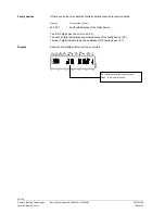
– – –
No valid sensor connected
2.4
Actual value of flow temperature
Temperature acquired with sensor B1/B12 in the flow of the mixing heating circuit is a
criterion for the control of the mixing valve.
Display
Unit
0...140
°C
2.5
Actual value of boiler temperature
Temperature acquired with sensor B2 in the boiler or by the BMU.
Display
Unit
0...140
°C
2.6
Actual value of common flow temperature
The common flow temperature is the flow temperature delivered by the relevant heat
source. When used as a heat generation controller, it is the flow temperature from the
boiler or from the buffer storage, depending on the type of plant. If the controller is
used in a zone, it is the actual value delivered via LPB.
Display
Unit
0...140
°C
Benefit
Sensor value
Effect
Special displays
Description
Setting
Description
Setting
Description
Setting

