6(77)
6.6.6
Check Half-yearly or Every 1000 Running Hours ....................... 77
6.6.7
3 year Checking.......................................................................... 77
Table Index
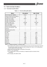
Table 1-1: Technical Specifications .................................................................. 12
Table 2-1: Parts List.......................................................................................... 23
Table 2-2: Cutting Mechanism Parts List .......................................................... 25
Table 2-3: Blades Assembly Parts List ............................................................. 27
Table 2-4: Driving Medium Parts List................................................................ 28
Table 2-5: Screen Parts List ............................................................................. 29
Table 2-6: Screen Frame Parts List .................................................................. 30
Table 2-7: Pushing Device Parts List................................................................ 32
Table 2-8: Hydraulic System Parts List............................................................. 35
Table 2-9: SGS-6080S Electrical Components List .......................................... 42
Table 2-10: Conveyor Belt Parts List (Matching in-SGS-6080S) ...................... 47
Table 3-1: Torque Forces of Blades and Other Fixing Screws ......................... 49
Picture Index
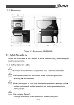
Picture 1-1: Dimensions (SGS-6080S) ............................................................. 13
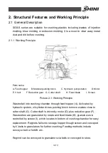
Picture 2-1: Working Principle .......................................................................... 19
Picture 2-2: Main Power Switch ........................................................................ 20
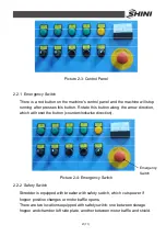
Picture 2-3: Control Panel................................................................................. 21
Picture 2-4: Emergency Switch......................................................................... 21
Picture 2-5: Screen Frame Safety Switch ......................................................... 22
Picture 2-6: Bolts .............................................................................................. 22
Picture 2-7: Assembly Drawing......................................................................... 23
Picture 2-8: Cutting Chamber Structure............................................................ 24
Picture 2-9: Blades Assembly........................................................................... 27
Picture 2-10: Driving Medium ........................................................................... 28
Picture 2-11: Screen Frame.............................................................................. 29
Picture 2-12: Pushing Device Assembly ........................................................... 31
Picture 2-13: Reduction Gear ........................................................................... 33
Содержание SGS-6080S
Страница 1: ...SGS S Single shaft Shredders Date May 2014 Version Ver B English...
Страница 2: ......
Страница 8: ...8 77...
Страница 24: ...24 77 2 3 3 Cutting Chamber Structure Picture 2 8 Cutting Chamber Structure...
Страница 31: ...31 77 2 3 12 Pushing Device Assembly Picture 2 12 Pushing Device Assembly...
Страница 34: ...34 77 2 3 15 Hydraulic System 2 3 15 1 Principle of Hydraulic System Picture 2 14 Principle of Hydraulic System...
Страница 37: ...37 77 2 4 Wiring Diagram 2 4 1 Wiring Diagram Picture 2 16 Wiring Diagram...
Страница 38: ...38 77 2 4 2 Control Wiring Diagram Picture 2 17 Control Wiring Diagram 1...
Страница 39: ...39 77 Picture 2 18 Control Wiring Diagram 2...
Страница 40: ...40 77 2 4 3 Electrical Components Layout Picture 2 19 Electrical Components Layout 1...
Страница 41: ...41 77 Picture 2 20 Electrical Components Layout 2...


