


7(77)
Picture 2-14: Principle of Hydraulic System...................................................... 34
Picture 2-15: Hydraulic Pump Station ............................................................... 35
Picture 2-16: Wiring Diagram............................................................................ 37
Picture 2-17: Control Wiring Diagram 1 ............................................................ 38
Picture 2-18: Control Wiring Diagram 2 ............................................................ 39
Picture 2-19: Electrical Components Layout 1 .................................................. 40
Picture 2-20: Electrical Components Layout 2 .................................................. 41
Picture 2-21: Main Electric Components........................................................... 44
Picture 2-22: Conveyor Belt.............................................................................. 45
Picture 2-23: Conveyor Belt Assembly Drawing (CB-3675).............................. 46
Picture 3-1: Installation Positions...................................................................... 50
Picture 3-2: Installation of Feed Hopper ........................................................... 51
Picture 3-3: Installation of Shield ...................................................................... 51
Picture 3-4: Installation of Main Cutter Shaft and Bearing ................................ 52
Picture 3-5: Installation of Main Cutter Shaft and Bearing 1 ............................. 52
Picture 3-6: Installation of Main Cutter Shaft and Bearing 2 ............................. 53
Picture 3-7: Installation of Main Cutter Shaft and Bearing 3 ............................. 53
Picture 3-8: Installation of Fixed and Rotate Blades ......................................... 54
Picture 3-9: Sieve Net and the Installation of a Screen..................................... 55
Picture 4-1: Installation of Screen Frame and Storage Hopper ........................ 60
Picture 4-2: Main Power Switch ........................................................................ 61
Picture 4-3: Emergency stop ............................................................................ 62
Picture 5-1: Oil Filler, Oil Pointer, and Vent ...................................................... 66
Picture 6-1: Adjustment of V-belt ...................................................................... 72
Picture 6-2: Bearing Oil Filler ............................................................................ 73
Picture 6-3: Oil Filling and Drain of Reduction Gear ......................................... 73
Picture 6-4
:
Anti-vibration Device .................................................................... 74
Содержание SGS-6080S
Страница 1: ...SGS S Single shaft Shredders Date May 2014 Version Ver B English...
Страница 2: ......
Страница 8: ...8 77...
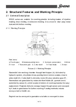
Страница 24: ...24 77 2 3 3 Cutting Chamber Structure Picture 2 8 Cutting Chamber Structure...
Страница 31: ...31 77 2 3 12 Pushing Device Assembly Picture 2 12 Pushing Device Assembly...
Страница 34: ...34 77 2 3 15 Hydraulic System 2 3 15 1 Principle of Hydraulic System Picture 2 14 Principle of Hydraulic System...
Страница 37: ...37 77 2 4 Wiring Diagram 2 4 1 Wiring Diagram Picture 2 16 Wiring Diagram...
Страница 38: ...38 77 2 4 2 Control Wiring Diagram Picture 2 17 Control Wiring Diagram 1...
Страница 39: ...39 77 Picture 2 18 Control Wiring Diagram 2...
Страница 40: ...40 77 2 4 3 Electrical Components Layout Picture 2 19 Electrical Components Layout 1...
Страница 41: ...41 77 Picture 2 20 Electrical Components Layout 2...


