56(77)
power line across left side hole in control cabinet to connect main power
switch.
Installation notices:
1) Please ensure that the voltage and frequency match with those marked on
name plate provided by the plant.
2) Connection of cables and ground wires shall accord with local regulations.
3) Please use independent cables and power switches and the diameter of
cables shall not be less than that of cables applied in electric cabinet.
4) Cable terminals shall be safe and fixed.
5) This series of machine requires three-phase four-wire power supply. Power
supply (L1, L2, L3) connects with live conductor and ground wire (PE).
6) Power distribution requirement:
Main power supply voltage:
±
10%
Main power supply frequency:
±
2%
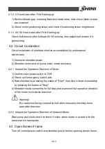
3.10.1 Inspect operation direction of motor
1) Check up if screen frame and feed hopper are well installed.
2) Inspect operation direction of motor:
3) Check up if emergency switch acts.
4) Start granulator by pressing the button of "Start"; then shut it down
immediately by pressing the button of "Stop".
5) Granulator needs some time for full stop and examine if the operation
direction of the motor is clockwise direction.
If the operation direction of the motor is incorrect, it is liable to damage
the blades. At the same time, it will also largely reduce the machine's
crushing capability! Please cut off power supply and change any two of
the three connection wires of the main power supply.
Be careful of crushing injuries when checking motor direction manually!
3.10.2 Inspect operation direction of hydraulic pump motor
1) Check if motor direction is in accord with the arrow mark.
2) Manually start hydraulic system then shut it down to observe motor direction.
Содержание SGS-6080S
Страница 1: ...SGS S Single shaft Shredders Date May 2014 Version Ver B English...
Страница 2: ......
Страница 8: ...8 77...
Страница 24: ...24 77 2 3 3 Cutting Chamber Structure Picture 2 8 Cutting Chamber Structure...
Страница 31: ...31 77 2 3 12 Pushing Device Assembly Picture 2 12 Pushing Device Assembly...
Страница 34: ...34 77 2 3 15 Hydraulic System 2 3 15 1 Principle of Hydraulic System Picture 2 14 Principle of Hydraulic System...
Страница 37: ...37 77 2 4 Wiring Diagram 2 4 1 Wiring Diagram Picture 2 16 Wiring Diagram...
Страница 38: ...38 77 2 4 2 Control Wiring Diagram Picture 2 17 Control Wiring Diagram 1...
Страница 39: ...39 77 Picture 2 18 Control Wiring Diagram 2...
Страница 40: ...40 77 2 4 3 Electrical Components Layout Picture 2 19 Electrical Components Layout 1...
Страница 41: ...41 77 Picture 2 20 Electrical Components Layout 2...


