FO-4400U
FO-CS1
3 – 22
b
c
d
e
h
f
g
h
d
e
f
a
a
b
c
g
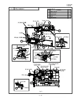
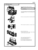
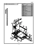
High voltage
PWB(HV1)
CN1
CN3
Cooling Fan
Motor
Fig. 15
15
High voltage PWB unit (HV1)
1. Remove the Cooling Fan Motor.(2 screws)
2. Remove the 2 covers. (9 screws)
3. Remove the 2 connectors.
4. Remove the High Voltage PWB.(2 screws)
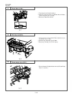
1. Remove the Paper Take-up Sensor (PS1). (1 connector)
Содержание FO 4400 - B/W Laser - All-in-One
Страница 125: ...FO 4400U FO CS1 Control PWB parts layout Top side 6 16 ...
Страница 126: ...FO 4400U FO CS1 Control PWB parts layout Bottom side 6 17 ...
Страница 128: ...FO 4400U FO CS1 LIU PWB parts layout Top side 6 19 ...
Страница 129: ...FO 4400U FO CS1 LIU PWB parts layout Bottom side 6 20 ...
Страница 132: ...FO 4400U FO CS1 Printer PWB parts layout Top side 6 23 ...
Страница 133: ...FO 4400U FO CS1 Printer PWB parts layout Bottom side 6 24 ...
Страница 135: ...FO 4400U FO CS1 Power Supply PWB parts layout 6 26 The Power supply PWB of this model employs lead free solder ...
Страница 143: ...FO 4400U FO CS1 M E M O 6 34 ...


