


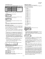

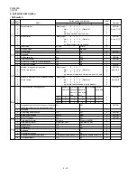

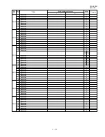


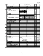


FO-4400U
FO-CS1
1
Memory retransmission times
Binary input
8
4
2
1
1
OPTION
2
No. =
1
2
3
4
(Data No.)
0
3
EX
1
0
1
0
1
SW10
4
eg. Retransmission time set to 10 times.
0
5
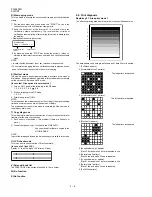
Memory retransmission interval
Binary input
8
4
2
1
0
OPTION
6
No. =
5
6
7
8
(Data No.)
0
7
EX
0
0
1
0
1
8
0
1
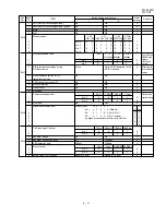
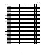
V.34 mode transmission speed
Sending speed = 2400 (bps) x (N+1)
1
2
Example :
1
3
2400 (bps) x 12 = 28800 (bps)
1
4
2400 (bps) is set for N=0. 33600 (bps) is set for N=14.
0
SW11
5
V.34 mode receiving speed
Receiving speed = 2400 (bps) x (N+1)
1
6
Example :
1
7
2400 (bps) x 12 = 28800 (bps)
1
8
2400 (bps) is set for N=0. 33600 (bps) is set for N=14.
0
1
V.34 mode function in case of manual communication On
Off
1
2
V.34 mode function
On
Off
1
3
V.34 control channel communication speed
2400bps
1200bps
0
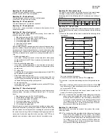
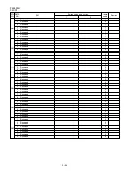
EOL detection timer
13sec
25sec
5sec
5sec
4
No. 4
0
0
1
1
0
SW12
5
No. 5
0
1
0
1
0
Processing of DIS reception after DIS
Command
A line is
Apply to
T.30+
α
transmission
retransmitting
cut
T.30
6
No. 6
0
0
1
1
0
7
No. 7
0
1
0
1
0
8
The change to DB from DP by
Yes
No
0
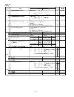
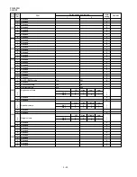
DTMF output level (High)
Binary input
16
8
4
2
1
For
For
No. =
1
2
3
4
5 (Data No.) n x 0.5dBm
U.S.A Canada
1
EX
0
1
1
0
0 (For U.S.A.)
0
0
2
EX
0
1
0
0
0 (For Canada)
1
1
3
eg. Signal transmission level is set to -10dBm
1
0
SW13
4
0
0
5
0
0
6
Reserved
0
7
Reserved
0
8
Reserved
0
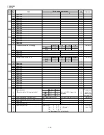
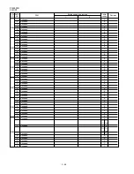
DTMF output level (Low)
Binary input
16
8
4
2
1
For
For
No. =
1
2
3
4
5 (Data No.) n x 0.5dBm
U.S.A Canada
1
EX
1
0
0
0
0 (For U.S.A.)
1
0
2
EX
0
1
1
0
0 (For Canada)
0
1
3
eg. Signal transmission level is set to -10dBm
0
1
4
0
0
SW14
5
0
0
6
Reserved
0
7
Reserved
0
8
Reserved
0
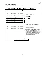
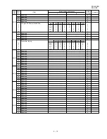
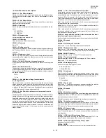
SW
NO.
DATA
NO.
ITEM
Switch setting and function
Remarks
Initial
setting
1
0
2 – 12
Содержание FO 4400 - B/W Laser - All-in-One
Страница 125: ...FO 4400U FO CS1 Control PWB parts layout Top side 6 16 ...
Страница 126: ...FO 4400U FO CS1 Control PWB parts layout Bottom side 6 17 ...
Страница 128: ...FO 4400U FO CS1 LIU PWB parts layout Top side 6 19 ...
Страница 129: ...FO 4400U FO CS1 LIU PWB parts layout Bottom side 6 20 ...
Страница 132: ...FO 4400U FO CS1 Printer PWB parts layout Top side 6 23 ...
Страница 133: ...FO 4400U FO CS1 Printer PWB parts layout Bottom side 6 24 ...
Страница 135: ...FO 4400U FO CS1 Power Supply PWB parts layout 6 26 The Power supply PWB of this model employs lead free solder ...
Страница 143: ...FO 4400U FO CS1 M E M O 6 34 ...


