FO-4400U
FO-CS1
[5] Installation
1. Site selection
Take the following points into consideration when selecting a site for this
model.
ENVIRONMENT
•
The machine must be installed on a level surface.
•
Keep the machine away from air conditioners, heaters, direct sun-
light, and dust.
•
Provide easy access to the front, back, and sides of the machine. In
particular, keep the area in front of the machine clear, or the original
document may jam as it comes out after scanning.
•
The temperature should be between 50
°
and 86
°
F (10
°
and 30
°
C).
•
The humidity should be between 30% and 85% (without condensa-
tion).
ELECTRICITY
AC 120 V, 60 Hz, grounded (3-prong) AC outlet is required.
Caution!
•
Connection to a power source other than that specified will cause
damage to the equipment and is not covered under the warranty.
•
If your area experiences a high incidence of lightning or power surges,
we recommend that you install a surge protector for the power and
telephone lines. Surge protectors can be purchased at most telephone
specialty stores.
TELEPHONE JACK
A standard RC11C telephone jack must be located near the machine.
This is the telephone jack commonly used in most homes and offices.
•
Plugging the fax machine into a jack which is not an RC11C jack may
result in damage to the machine or your telephone system. If you do
not know what kind of jack you have, or need to have one installed,
contact the telephone company.
If the machine is moved from a cold to a warm place...
If the machine is moved from a cold to a warm place, it is possible that
the reading glass may fog up, preventing proper scanning of documents
for transmission. To remove the fog, turn on the power and wait approxi-
mately 2 hours before using the machine.
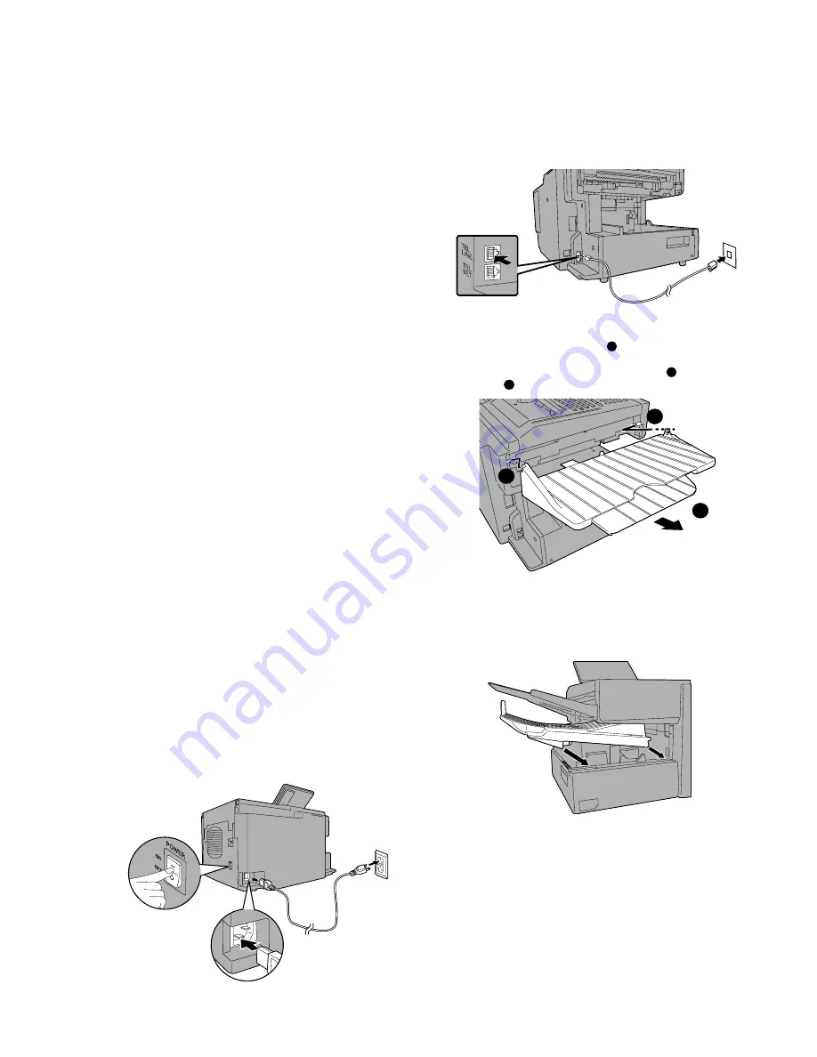
2. Assembly and connections
1
Connecting the power cord
Connect the female end of the power cord to the fax machine as
shown. Insert the male end into a 120 V, 60 Hz, grounded (3-prong)
AC outlet.
Important!: The fax machine requires its own dedicated power outlet.
The power outlet must not be shared with any other devices. In particu-
lar, do not use an extension cord to connect multiple devices to the
outlet.
Note: If your area experiences a high incidence of lightning or power
surges, we recommend that you install surge protectors for the power
and telephone lines. Surge protectors can be purchased at most tel-
ephone specialty stores.
3
Attaching the ADF exit tray
Insert the protrusion on the right side of the machine into the hole in
the right side of the ADF exit tray
1
, then bend the tray slightly and
insert so that the protrusion on the left side of the machine goes into
the hole on the left side of the ADF exit tray
2
. Pull out the tray
extension
3
.
Press the power
switch to turn on
the power.
2
Connecting the telephone line cord
Insert one end of the line cord into the jack on the back of the ma-
chine marked TEL. LINE. Insert the other end into a standard (RJ11C)
single-line wall telephone jack.
Note: The fax machine is set for touch-tone dialing. If you are on a pulse
dial (rotary) line, you must set the fax machine for pulse dialing by chang-
ing Option Setting 22.
1
3
2
4
Attaching the received document tray
Slide the received document tray into the machine as shown. When
it stops, lift the end slightly and push in so that the tray locks into
place.
Important!: The received document tray must be attached for the fax
machine to operate properly.
5
Verification Stamp option (FO-45VS)
Note: This feature is available as an option. Consult your dealer if
you wish to use this feature.
When transmitting a document, you can have the fax machine stamp
each document page as it is scanned. After scanning, you can check
to see if all document have been stamped to verify that no double
feeds occurred. (A double feed occurs when two pages are fed through
the scanner at once, which means that one of the pages is not
scanned.)
To use this function, have your dealer install the Verification Stamp
option, and then set Option Setting 29 to ON.
1 – 4
Содержание FO 4400 - B/W Laser - All-in-One
Страница 125: ...FO 4400U FO CS1 Control PWB parts layout Top side 6 16 ...
Страница 126: ...FO 4400U FO CS1 Control PWB parts layout Bottom side 6 17 ...
Страница 128: ...FO 4400U FO CS1 LIU PWB parts layout Top side 6 19 ...
Страница 129: ...FO 4400U FO CS1 LIU PWB parts layout Bottom side 6 20 ...
Страница 132: ...FO 4400U FO CS1 Printer PWB parts layout Top side 6 23 ...
Страница 133: ...FO 4400U FO CS1 Printer PWB parts layout Bottom side 6 24 ...
Страница 135: ...FO 4400U FO CS1 Power Supply PWB parts layout 6 26 The Power supply PWB of this model employs lead free solder ...
Страница 143: ...FO 4400U FO CS1 M E M O 6 34 ...


