FO-4400U
FO-CS1
6. Installing the paper cassette (FO-CS1)
Installing the second paper cassette
Important: Be sure to turn off the power and unplug the power cord
before proceeding.
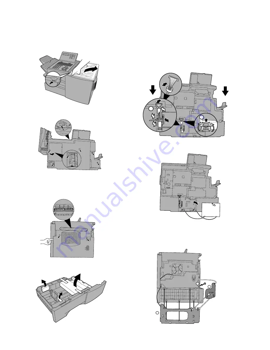
1
Press the cover release to open the print compartment cover.
2
Remove 6 screws from the rear cover.
Remove the small cover on the left side of the rear cover, and then
remove the screw underneath. Remove the rear cover.
3
Remove 2 screws from the right cover of the machine.
From inside the print compartment, push the 3 tabs indicated in the
blowup out. (Note: The blowup shows the inside of the print compart-
ment.) Insert your left index finger in between the cover and the ma-
chine as shown, and then close the print compartment cover. With
your index finger still inserted, grasp both sides of the cover and pull
it off.
4
Remove the packing material and tape from the paper cassette.
5
Place the machine on top of the cassette.
1. Insert the cable guide into the cut-out in the edge of the metal
plate, and then fold it in half and hook the top and bottom edges
together.
2. Insert the 15pin cable through the ferrite core, and then connect
the cable to the connectors on the machine and the cassette as
shown. Position the ferrite core in the gap between the bottom
left-hand corner of the circuit board and the side of the
compartment. Insert the cable into the cable guide, and then
insert the remainder of the cable into the slot in the cassette
below the cable guide. Tie the wires with the band.
2
1
6
Replace the small cover over the circuit board and secure it with a
10 mm screw.
P
7
Attach the support plates to the right side of the machine.
1. Remove the indicated screw.(In Step 8 below, replace it in the
same hole.)
2. Mount the large plate, making sure that the guides fit into the holes
as shown.
3. Mount the small plate, making sure that the guides fit into the holes
as shown.
A
1
3
2
1 – 9
Содержание FO 4400 - B/W Laser - All-in-One
Страница 125: ...FO 4400U FO CS1 Control PWB parts layout Top side 6 16 ...
Страница 126: ...FO 4400U FO CS1 Control PWB parts layout Bottom side 6 17 ...
Страница 128: ...FO 4400U FO CS1 LIU PWB parts layout Top side 6 19 ...
Страница 129: ...FO 4400U FO CS1 LIU PWB parts layout Bottom side 6 20 ...
Страница 132: ...FO 4400U FO CS1 Printer PWB parts layout Top side 6 23 ...
Страница 133: ...FO 4400U FO CS1 Printer PWB parts layout Bottom side 6 24 ...
Страница 135: ...FO 4400U FO CS1 Power Supply PWB parts layout 6 26 The Power supply PWB of this model employs lead free solder ...
Страница 143: ...FO 4400U FO CS1 M E M O 6 34 ...


