FO-4400U
FO-CS1
3 – 24
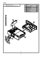
Fig. 18
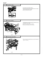
1. Place the printer with its backside down.
2. Unhook the spring and remove the right-hand side of the Paper
Take-up Roller shaft from its bushing.
3. Remove the Paper Take-up Roller.
17
Paper take-up roller
(a)
(b)
(c)
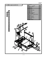
Fig. 17
18
Print head unit (PH)
19
Paper empty sensor (PE1)
1. Unplug the connector from the Main Motor Unit and remove the
harness from the cord holder.
2. Unplug the connectors from the cord holder.
3. Remove the Print Head Unit (PH). (6 screws)
Fig. 19
1. Remove the sensor fixing bracket and remove the Paper Empty
Sensor. (1 connector)
Содержание FO 4400 - B/W Laser - All-in-One
Страница 125: ...FO 4400U FO CS1 Control PWB parts layout Top side 6 16 ...
Страница 126: ...FO 4400U FO CS1 Control PWB parts layout Bottom side 6 17 ...
Страница 128: ...FO 4400U FO CS1 LIU PWB parts layout Top side 6 19 ...
Страница 129: ...FO 4400U FO CS1 LIU PWB parts layout Bottom side 6 20 ...
Страница 132: ...FO 4400U FO CS1 Printer PWB parts layout Top side 6 23 ...
Страница 133: ...FO 4400U FO CS1 Printer PWB parts layout Bottom side 6 24 ...
Страница 135: ...FO 4400U FO CS1 Power Supply PWB parts layout 6 26 The Power supply PWB of this model employs lead free solder ...
Страница 143: ...FO 4400U FO CS1 M E M O 6 34 ...


