Rostock MAX v2 Assembly Guide – 4thEd.
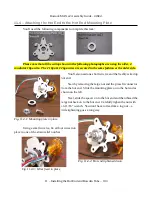
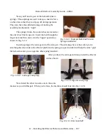
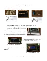
Start with the left side first – the narrow end of the support fits into the front panel as shown
below. Make sure that you've got the front panel oriented properly – the tab pointed to by the arrow
should be pointing down when the front panel his held vertically.
Press the tab into place until the mount is flush
with the face of the front panel as shown. Fix in place
with a #6-32 pan head screw.
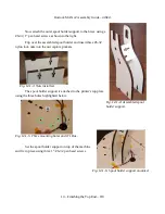
Now install the right side and fix it in place with
another #6-32 pan head screw.
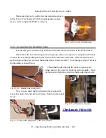
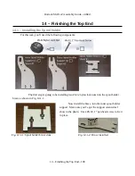
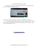
Now you can attach the LCD control panel to the
mounts. Orient the LCD panel as shown so that the SD
card socket matches the notch for it.
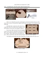
Attach the LCD panel to the mount using four #2-56, 5/8” screws.
16 – Assembling & Installing the LCD Panel Mount – 117
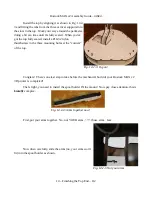
Fig. 16.1-2: Installing the left side.
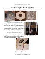
Fig. 16.1-3: Left side ready for a screw.
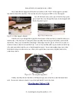
Fig. 16.1-4: LCD panel orientation.
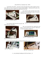
Fig. 16.1-5: Ready for screws!
Fig. 16.1-6: Right side.
Fig. 16.1-7: Left side done.

