Rostock MAX v2 Assembly Guide – 4thEd.
8.7 – Connecting the End Stop Switches
For this task, you'll be routing the end-stop wires to the end-stop switches and connecting them
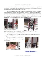
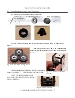
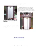
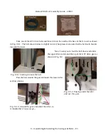
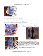
up. At the “front” of each tower there is a small, triangular shaped opening that you're going to pass
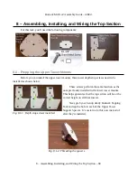
the end stop switch wires through. We'll start with the Z axis. Pull the leads you labeled “Z” across
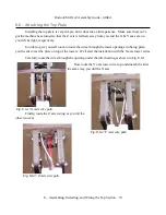
from the Y axis and route them through the hole shown in Fig. 8.7-1. If you need more wire to reach,
gently pull it up at the top of the Y tower. You may need to lift the tower a little bit to lessen the bend
radius the wire needs to feed.
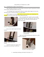
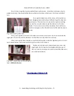
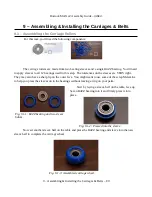
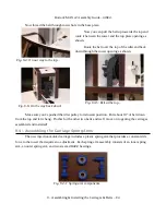
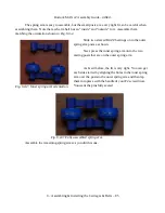
Now carefully seat each spade lug connector on to the end stop switch as shown below. It
doesn't matter where the white & black wires go, just as long as one is on the innermost spade lug and
the other the outermost.
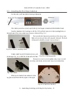
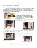
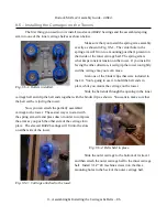
Repeat this process for the X and Y towers.
Once all three towers are done,
carefully
pull the
wires at the bottom of the tower to pull out the slack in
the Z and X axis end stop wires. Don't pull them too
tight – you just want the wires to be fairly straight.
8 – Assembling, Installing, and Wiring the Top Section – 76
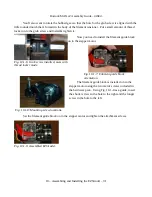
Fig. 8.7-1: Z axis end stop wire hole.
Fig. 8.7-2: Z axis wires ready to plug in.
Fig. 8.7-3: Z axis end stop switch wired.
Fig. 8.7-4: End stops connected.

