40
SECTION 12 SYSTEM INPUT CONNECTIONS
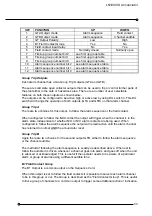
Alarm inputs - Hazardous areas
The alarm contacts to be connected to the annunciator may be located in any hazardous
area but must meet the requirements defined for simple apparatus in Clause 5.4 of BS
EN50020:1995. Because these alarm contacts are switching such low currents and voltages
they should be of a suitably high quality with a specification suitable for switching signals of
5VDC and 250uA. Each contact should be wired as a conductor pair using either two core or
suitable multi-pair screened cable. Cable parameters are listed in Appendix A.
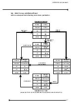
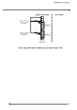
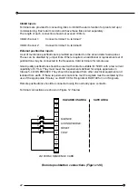
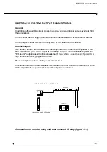
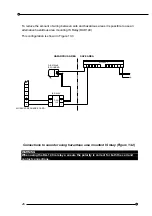
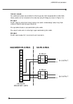
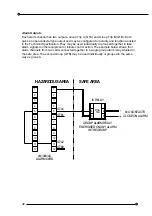
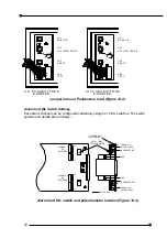
Usually, normally closed (open to alarm) contacts are used and these are wired as shown in
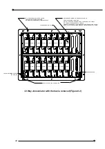
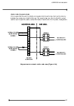
Figure 12.1. If normally open (close to alarm) contacts are used the terminal connections are
as shown in Figure 12.2
Alarm ways wired with normally closed contacts (Figure 12.1)
6
CHANNEL 2
ALARM CONTACT
NORMALLY CLOSED
12
LN1000/AC
ALARM CARD
9
11
10
8
7
LOWER
WINDOW
CHANNEL 1
ALARM CONTACT
NORMALLY CLOSED
HAZARDOUS AREA
3
5
4
2
1
WINDOW
UPPER
SAFE AREA


