10
SECTION 3 INPUTS & OUTPUTS
Terminations and interconnections
All connections to the LN1000 Annunciator are via rear mounted screw terminals. These
terminals are suitable for cables up to 2.5mm².
In the wall mounted versions the input and output terminals are wired to a row of
2.5mm²terminals on the backplane.
The Sequence Card and the Alarm Cards are all interconnected by a common backplane.
This backplane is used to supply power to the Alarm Cards, synchronise the flashing of the
LED’s, ascertain the first-up alarm in any sequence, connect the pushbutton controls and
provide a drive signal to the local horn, the external sounder outputs and all group outputs.
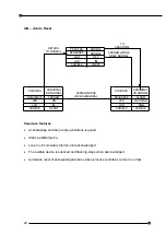
LN1000-AC Alarm Card
The Alarm Card monitors two alarm channels and each channel has the following inputs and
outputs:
ALARM INPUT:
CONNECTED TO THE VOLT-FREE ALARM CONTACTS
INHIBIT INPUTS:
Connected To Volt-Free Contacts To Inhibit That Alarm Channel
GROUP A OUTPUT:
Configurable To Follow The Alarm Logic Or The Field Contact
GROUP B OUTPUT:
Configurable To Follow The Alarm Logic Or The Audible
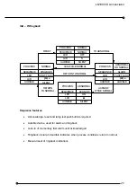
LN1000-SC Sequence Card
Each system will have a Sequence Card which monitors and controls the common functions
as follows:-
PUSHBUTTON
INPUTS:
FOR TEST, ACKNOWLEDGE, RESET AND SILENCE
PUSHBUTTONS
HORN OUTPUT:
Not Used
EXT SOUND:
This Output Is Used To Drive An Is Relay, Which In Turn Will Switch
External Higher Level Audible Devices.
B1 OUTPUT:
Configurable To Follow The Alarm Logic Or Field Contacts
B2 OUTPUT:
Reflash Output Gives A One Second Pulse On New Alarms


