36
SECTION 9 FIELD WIRING
Certification
The LN1000 IS Annunciator system must be installed and wired in accordance with the
requirements of the IS System certificate and IS codes of practice. This document should be
read along with the associated equipment certificates and drawings before proceeding
further. Copies of these drawings and certificates are available on request from RTK
Instruments Ltd
General
All field wiring to the annunciator should use screened cable. The screening must be
securely terminated using ring terminals on the studs provided. The removable cable housing
should be drilled for user supplied gland fittings.
Access to the annunciator terminals is achieved by removal of the rear cover on the cable
housing. The terminal blocks form part of the edge connector for each card.
All wiring must meet the Cable Parameter requirements detailed in Appendix A.
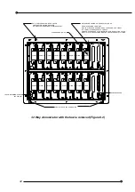
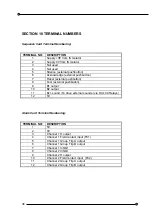
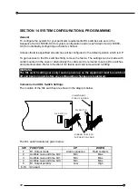
The terminals are clearly marked on the backplane as to their function i.e. AL1, AL2 etc for
the Alarm Cards and Sequence Card are marked as such. The individual terminals for each
block are numbered 1 to 12.
The terminal connectors are clipped into the backplane.
These should not be removed
from the backplane during wiring.
Check the connectors are still correctly clipped into the
backplane on completion of wiring.
Rear view of the 12 way annunciator showing the terminals (Figure 9.1)
1
AL 5
1
12
F
.E
.C CA
R
D
S
E
Q
U
E
NCE
CA
RD
J1
1
J2
12
1
12
12 J3
1
12
1
J4
J5
12
1
J6
12
1
J7
1
1
AL 1
1
AL 2
1
AL 3
1
AL 4
1
12
J8
1
AL 6
1
CABLE HOUSING RETAINED BY 6 OFF M3 THUMB SCREWS.
ALL PANEL MOUNTING SCREWS ARE
ACCESSIBLE WITH REAR PANEL REMOVED.
SCREWS ARE CAPTIVE TO MOUNTING BRACKETS.
M4 CHASSIS EARTH STUD TERMINATIONS.
CONNECTOR TERMINALS
SUITABLE FOR
CONDUCTORS UP TO 5mm.


