12
LN1000-AC Alarm Card
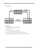
Each alarm card has two independent alarm channels
Alarm
Inputs
Alarm contacts
Isolated volt free contacts, may be normally open or
normally closed, selectable by DIL switch
Normally closed contacts
Field contact wired between H (+ve) and FC
Normally open contacts
Field contact wired b5V and FC linked to H
Applied voltage (open contact)
5VDC typical
Current (closed contact)
250 micro amps typical
Inhibit Inputs
Inhibit contacts
Isolated, volt free contacts, closed to inhibit
Applied voltage (open contact)
5VDC typical
Alarm Outputs
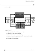
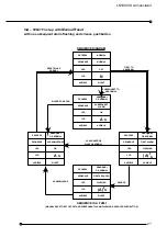
Group Trip A Output (GTA)
Configurable:
(a) Follows alarm logic
(b) Follows field contact
Group Trip B Output (GTB)
Configurable:
(a) Follows alarm logic
(b)
Follows
audible
Group Trip Outputs (A and B)
The above two outputs are configurable as
energised or de-energised on alarm.
(a) Low for normal
(b) Low for alarm
Option (a) or (b) must be the same for both GTA
and GTB outputs of each channel
Group Output voltage
Both outputs are current sinking through a 10k
resistor and a series diode for switching DAA149,
DAB149 and DAD149 relays.
WARNING
The maximum number of DA-149 is relays driven from one system should not exceed
35 and the maximum number of relays driven from a single output should not exceed
2.


