50
SECTION 14 SYSTEM CONFIGURATION & PROGRAMMING
General
To configure the system for your particular requirements DIL switches are set on the
Sequence Card (LN1000-SC) for system configuration and on each Alarm Card (LN1000-
AC) for individually configuring each alarm channel.
Unless otherwise specified all switches will be configured in the default position which is UP
To gain access to the DIL switches firstly remove the fascia. The settings can be made with
cards mounted in the case or alternatively the cards can be removed to set up DIL switches
and potentiometers. Refer to Section 8 for fascia and card removal and re-fitting
WARNING
The DIL switch settings are only read on power up so the equipment must be switched
off and back on again before any configuration changes are registered.
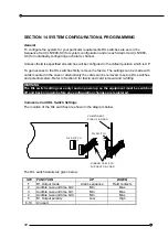
Commons Card DIL Switch Settings
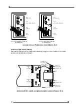
The location of the DIL switches are shown in the diagram below.
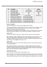
The DIL switch details are given below:
SW FUNCTION
UP
DOWN
1
B1 Output mode
Alarm sequence
Field contacts
2
Audible re-sound time bit 2
Min
Max
3
Audible re-sound time bit 1
Min
Max
4
Audible re-sound time bit 0
Min
Max
5
B1 Output polarity
Low
High
6-10 Unused
10
1
10
1
R IBBO N C ABLE TO
PU SH BUTO N CARD
DIL SW ITCH
C O M PO N ENT
SID E OF BO ARD
D IL SW ITCH


