44
Inhibit Inputs
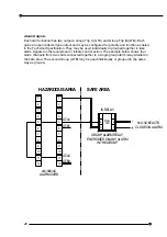
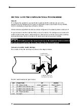
Terminals are provided for connecting links to inhibit the alarm function for plant start up or
commissioning. Each alarm card should have these links wired separately.
The length of each connection should not exceed 100mm.
Inhibit channel 1:
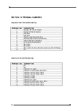
Connect terminal 1 to terminal 7
Inhibit channel 2:
Connect terminal 1 to terminal 8
External pushbutton inputs
A set of membrane pushbuttons is provided as standard on the annunciator fascia panel.
These can be disabled by jumper links. Where required, an additional or replacement set of
pushbuttons may be connected to the Sequence Card terminals for remote use.
Good quality pushbuttons should be used with contacts suitable for 5VDC with a low current
capability of 0.1mA. They must meet the requirements defined for simple apparatus in
Clause 5.4 of BS EN50020. They should be separated from other electrical equipment and
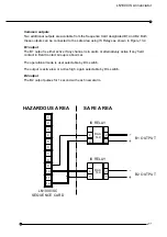
isolated from earth. If these requirements cannot be met the signals must be isolated by the
use of the appropriate IS relay, i.e. DAD149 for IS signals or DAE149 for non IS signals.
Remote pushbuttons should be connected using the normally open contacts.
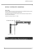
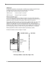
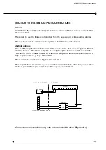
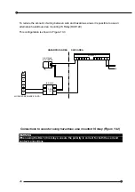
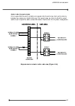
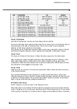
Terminal connections are shown in Figure 12.5 below
Remote pushbutton connections (Figure 12.5)
LN1000/SC SEQUENCE CARD
HAZARDOUS AREA
RESET
ACKNOWLEDGE
SILENCE
7
T
12
11
10
9
8
TEST
R
A
S
3
6
5
4
2
1
SAFE AREA


