2A3/4
3-6-80
(24)
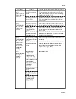
The eject
speed
switching
clutch does
not operate.
(25)
The bypass
solenoid does
not operate.
(26)
The cleaning
lamp does not
turn on.
(27)
The exposure
lamp does not
turn on.
Broken eject
speed switching
clutch coil.
Poor contact in the
eject speed
switching clutch
connector
terminals.
Defective engine
PCB.
Broken bypass
solenoid coil.
Poor contact in the
bypass solenoid
connector termi-
nals.
Defective engine
PCB.
Poor contact in the
cleaning lamp con-
nector terminals.
Defective cleaning
lamp.
Defective engine
PCB.
Poor contact in the
exposure lamp
connector
terminals.
Defective inverter
PCB.
Defective scanner
motor PCB.
Check for continuity across the coil. If none,
replace the eject speed switching clutch.
Reinsert the connector. Also check for
continuity within the connector cable. If
none, remedy or replace the cable.
Run maintenance item U032 and check if
CN3-A11 on the engine PCB goes low. If
not, replace the engine PCB.
Check for continuity across the coil. If none,
replace the bypass solenoid.
Reinsert the connector. Also check for
continuity within the connector cable. If
none, remedy or replace the cable.
Run maintenance item U033 and check if
CN14-A8 on the engine PCB goes low. If
not, replace the engine PCB.
Reinsert the connector. Also check for
continuity within the connector cable. If
none, remedy or replace the cable.
Check for one-way continuity across each
LED comprising the cleaning lamp. If none,
replace the cleaning lamp.
If the cleaning lamp turns on when CN2-A2
on the engine PCB is held low, replace the
engine PCB.
Reinsert the connector. Also check for
continuity within the connector cable. If
none, remedy or replace the cable.
If the exposure lamp does not turn on when
CN1-5 and CN1-6 on the inverter PCB are
held low, replace the inverter PCB.
If the exposure lamp turns on when CN3-1
and 3-2 on the scanner motor PCB are held
low, replace the scanner motor PCB.
Problem
Causes
Check procedures/corrective measures
Содержание Ri 4230
Страница 1: ...4230 5230 S M MCA SERVICE MANUAL Published in June 00 2A370941 Revision 1 Ri 4230 5230 Ri 4230 5230 ...
Страница 3: ...SERVICE MANUAL Ri 4230 5230 ...
Страница 13: ...4230 5230 S M MCA THEORY AND CONSTRUCTION SECTION I I Theory and Construction Section ...
Страница 14: ...1 1 5 2A3 4 CONTENTS 1 1 Specifications 1 1 1 Specifications 1 1 1 ...
Страница 21: ...1 1 7 2A3 4 CONTENTS 1 2 Handling Precautions 1 2 1 Drum 1 2 1 1 2 2 Developer and toner 1 2 1 ...
Страница 100: ...4230 5230 S M MCA ELECTRICAL SECTION II II Electrical Section ...
Страница 119: ......
Страница 138: ......
Страница 159: ...4230 5230 S M MCA III Set Up and Adjustment Section III SET UP AND ADJUSTMENT SECTION ...
Страница 419: ...1 1 25 2A3 4 CONTENTS 3 5 Self Diagnosis 3 5 1 Self diagnosis 3 5 1 1 Self diagnostic function 3 5 1 ...
Страница 448: ...2A3 4 3 6 3 25 Toner scatters at the leading edge of the image See page 3 6 17 ...


