


C O M M U N I C A T I O N S
Ethernet Control
350-10035-01 v4.1.1
Linx DVI Matrix Switchers User’s Guide
25
3.
Select
Serial
and the
Port
to be used.
4.
Click
OK
. The terminal window opens.
5.
From the
Setup
menu, select
Serial Port
.
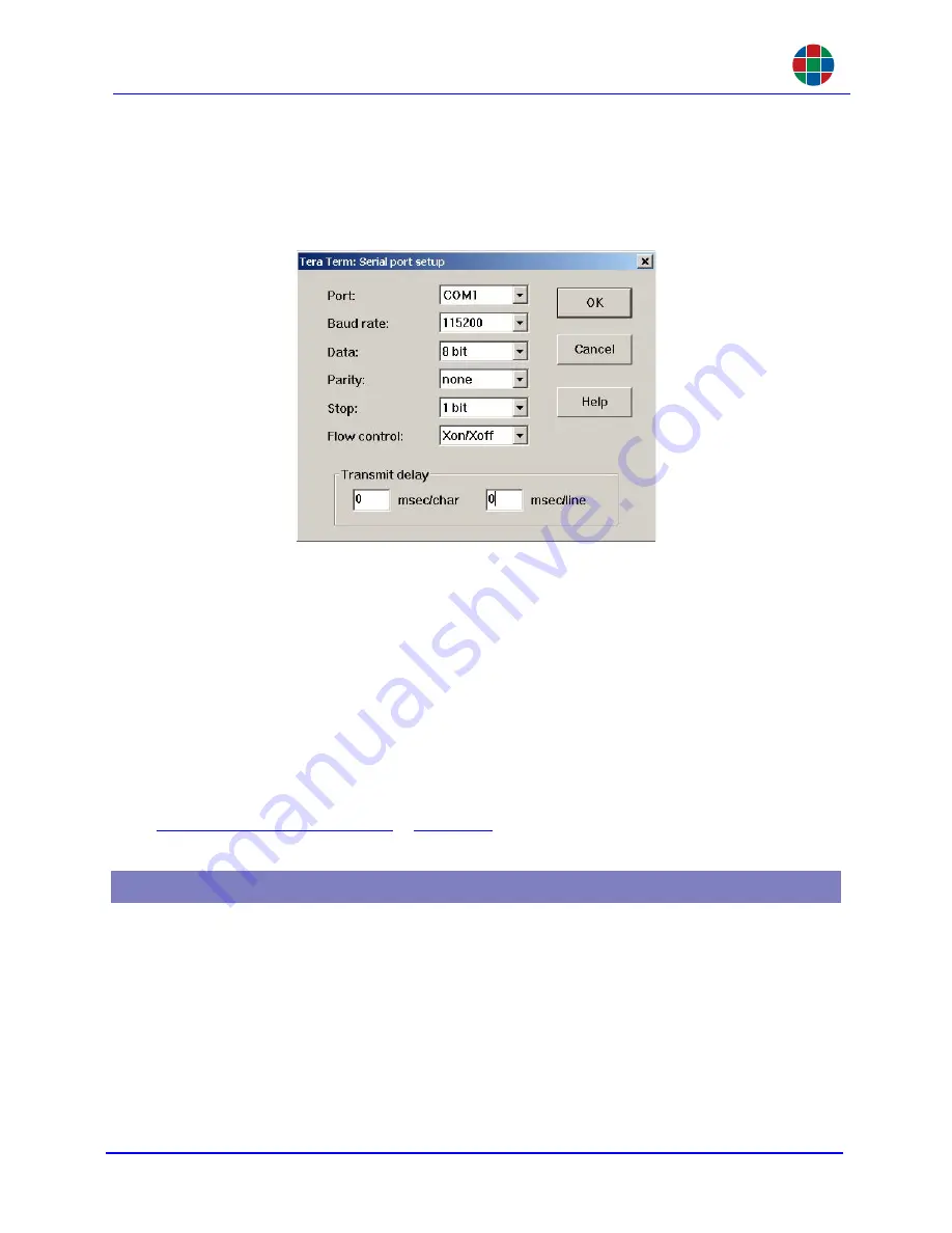
Figure 3-2
Serial Port Setup
6.
Set the communication parameters to match those of the
Linx DVI Switcher
. In Figure 3-2 the
Linx DVI Switcher
default values have been used.
7.
Click
OK
.
8.
Confirm the communication with the
Linx DVI Switcher
by typing
ver
and pressing
ENTER
.
The current firmware version should be displayed. If not, check the settings outlined above
and repeat.
The
Linx DVI Switcher
may now be controlled through the serial port.
For details on how to change the baud rate or other serial communications settings please refer to
Communications Commands
in
Chapter 6
.
The
Linx DVI Switcher
can be controlled from the 100/1000 BASE-T Ethernet port using either the
graphical user interface (WCP), a command line terminal operated from the graphical interface, or
Telnet. The graphical interface uses a standard web browser such as Microsoft Internet Explorer;
the
Linx DVI Switcher
can be connected to a standard LAN or directly as a peer-to-peer connection.
The command line interface uses a Telnet session to a private port.
The IP Address of a Linx Switcher can always be viewed via the front panel display. Turn the scroll
knob until the desired information is displayed.
3.2 Ethernet Control


