*Notice: The information in this document is subject to change without notice
Tsi301
Notes
Tsi301 HyperTransport to PCI User Manual
3-20
same channel. Re-allocation guarantees that the minimum allocation set in the Need CSR fields will always be
met as long as the sum of the CSR values is less than or equal to the total number of data buffers in the link
interface.
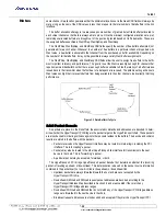
The buffer allocation strategy is to always keep some number of granted but unfilled buffers allocated to
each virtual channel so that data is always able to move. Once the minimum configured allocations are met,
remaining unallocated buffers are brought out of the pool and granted based on traffic demands. These are
the assigned buffers specified in WantPReq, WantNpReq, and WantResp.
The WantPReq, WantNpReq, and WantResp CSR fields specify the number of free buffers attempted (not
guaranteed) for each channel. Whenever the number of free buffers in a particular channel drops below its
Want value, a new buffer is allocated to that channel from the pool based on buffer availability. Depending on
the number of full data buffers, it may not be possible to always satisfy Want buffer assignments.
The WantPReq, WantNpReq, and WantResp CSR fields allow the user to assign free buffers to the traffic
most important to latency and performance. The goal is to set the Want values high enough for channels that
require maximum bandwidth so that there are enough buffers available to hide the latency of a buffer release
issued back to the transmitter when the first beat of a data packet is received. The pitfall is setting a channel’s
Want values so high that it prevents buffers from being available to the other channels, inadvertently throttling
performance.
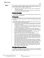
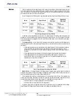
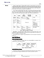
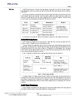
Figure 3.3 Data Buffer Life Cycle
3.2.2 Packet Decode
As packets are placed in the Rx buffers, the associated commands and addresses are decoded to deter-
mine whether the HyperTransport PCI bridge is the packet target on the HyperTransport chain. These packets
are also checked for ordering collisions against other packets resident in the buffers. The decode and collision
results are stored in the buffers with the packets.
•
Packets received on the HyperTransport interface may be routed to internal logic, including the PCI
interface. This is “accepting” a packet.
•
Packets may also be routed to the other HyperTransport link interface for transmission to the next
device in the chain. This is “forwarding” a packet.
•
A particular packet may be accepted, forwarded, or both.
The HyperTransport PCI bridge HyperTransport packet decode first determines whether the incoming
packet is travelling upstream or downstream. This determination is based on the packet source information
contained in the packet itself, not on which link is the upstream or downstream link.
•
Upstream packets are always forwarded toward the host and are never accepted by the
HyperTransport PCI chip.
•
Downstream RdSized and WrSized request packet addresses are decoded according to the
HyperTransport Address Map described in Section 3.3 and are accepted if they match any
HyperTransport PCI bridge address ranges.
•
Downstream WrSized and RdSized that do not match any of the HyperTransport PCI bridge address
ranges are forwarded to the next device in the chain.
•
Broadcast request addresses are also decoded and accepted if they match a HyperTransport PCI


