*Notice: The information in this document is subject to change without notice
Tsi301
Notes
Tsi301 HyperTransport to PCI User Manual
4-6
Note:
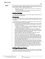
Test assumes tmode and/or bypass enable on core clock is active.
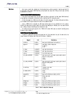
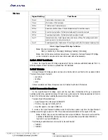
4.2.2 Resets
Note:
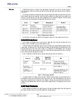
1.All resets are asynchronously asserted and synchronously deasserted to the specified
clock.
2.ColdReset is delayed so that the PLL has time to lock before reset is released.
3.ColdReset is sent to the PHY and synchronized to the link data clock (clock from the
PLL).
The result is ldtTxWlnkRst_N and is used to reset some link data clock logic as well as the
WlnkClk.
4.3 Performance Information
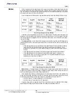
The following clocks are referenced in this section:
LDT Rx Clock = Lx_RX_CLK_H/L clock period (twice the HyperTransport bit time)
LDT Tx Clock = Lx_TX_CLK_H/L clock period (twice the HyperTransport bit time)
Core Clock = Period of the clock used for HyperTransport PCI Bridge core
Times are given from the first piece of the packet presented on one interface to the first piece of the packet
being presented on the next interface. For the HyperTransport interface, this is the first byte of the packet on
the link.
4.3.1 Inbound Operations
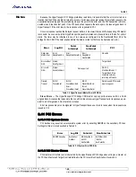
Latency through the HyperTransport PHY from the first byte of the packet on the link to the clock edge
where the Rx Sync FIFO captures the doubleword of data = 3 * LDT Rx Clock + data alignment factor
Note:
For an 8-byte header, the two 4-byte halves can be received aligned (so that they are
received by the core in the same core clock cycle) or unaligned (split across two core clock cycles).
For headers received aligned, there is an additional delay defined as the data alignment factor in the
equation. This value can range from 0 to ((1*Core Clock) + (2*LDT Rx Clock)).
Minimum latency through Rx Sync FIFO = (2 * Core Clock) + clock alignment factor. Actual latency
depends on SIP settings for Rx Sync FIFO.
Note:
For the two clock domain crossings in the receive direction, there is a clock alignment factor
in the calculation that can range from 0 to ((2 * Core Clocks) + (1 LDT Rx Clock)).
Latency from Rx Sync FIFO through the Rx buffers to the header presented at the HyperTransport receive
interface = 2 * Core Clock
Clock
Description
Sync
1
Pin
coldReset_N
L_POWER_OK delayed by 0.5 ms
2
clk
L_TSTRST_N
warmReset_N
Derived from L_RST_N
clk
L_TSTRST_N
rstClkDiv_N
Derived from L_POWER_OK
refclk
L_TSTRST_N
ldtRxWlnkRst_N
Synchronized warmReset_N
ldtRxWlnkClk
L_TSTRST_N
ldtTxWlnkRst_N
Synchronized coldReset_N
3
ldtTxWlnkClk
L_TSTRST_N
ldtRxLoadPtrRst_N
Derived from ldtRxSync
ldtRxWlnkClk
L_TSTRST_N
ldtRxUnloadPtrRst_N
Link Synchronized ldtRxSync
clk
L_TSTRST_N
Table 4.3 HyperTransport PCI Bridge Internal Resets

