Operating the Instrument
R&S
®
RTO2000
83
Getting Started 1332.9719.02 ─ 10
To arrange the diagrams on the screen, the Rohde & Schwarz SmartGrid function
helps you to find the target place simply and quickly. For details, see
on page 91. You can also adjust the diagram
size by dragging the diagram border.
Grid (2)
The grid shows the vertical and horizontal divisions. The division lines are labeled
with the correspondent values. The grid labels have the color of the waveform to
which they belong. If several waveforms are shown in one diagram, the grid has
the color of the selected waveform.
Sidebar (3)
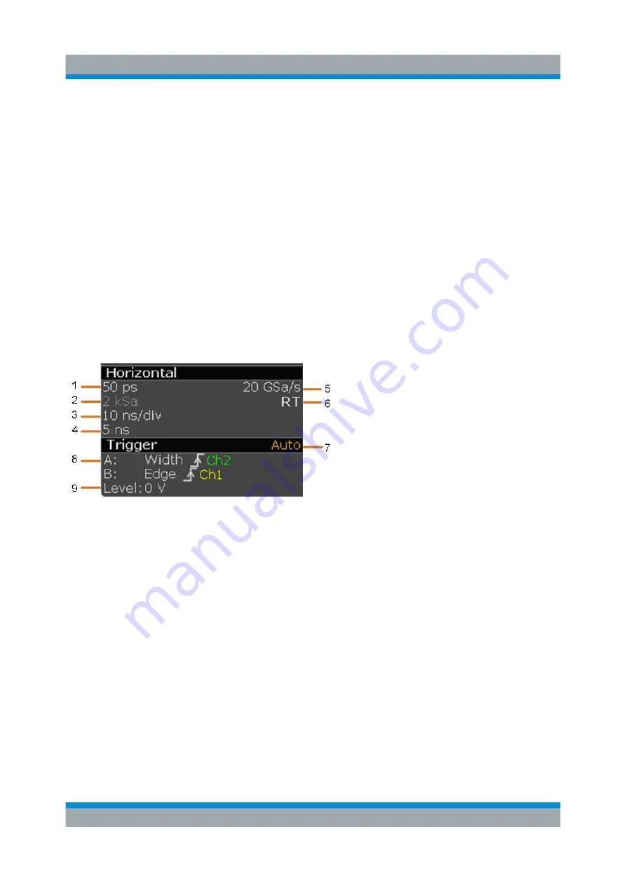
The sidebar is the control center for all enabled waveforms. On the top, the hori-
zontal and trigger labels show the main timebase and trigger settings. If you tap a
label, the relevant dialog box opens with the tab used at last.
Figure 7-2: Horizontal and trigger label on top of the sidebar
1 = Resolution
2 = Record length
3 = Timebase (horizontal scale)
4 = Horizontal position
5 = Sample rate
6 = RT - real time, IT - interpolated time
7 = Trigger mode
8 = Trigger type, slope or polarity, source for A-event and B-event
9 = Trigger level
Below, each waveform is represented by a signal icon. If the waveform is shown
in a diagram, the signal icon displays its main vertical and acquisition settings. If
you tap the "Minimize" icon on the signal icon, the waveform switches from the
diagram area to the signal icon: the icon shows the real-time preview of the wave-
form. If you tap a signal icon, the dialog box with vertical settings for this wave-
form opens. See
Chapter 7.4, "Working with Waveforms"
detailed description.
Touchscreen Display


