Measurements R&S
FSH
1145.5973.12 4.162
E-14
The video filter comes after the envelope detector. The filter is a lowpass with an adjustable cutoff
frequency which limits the bandwidth of the video signal. It is particularly useful when sine signals are to
be measured in the vicinity of the spectrum analyzer’s intrinsic noise. The sine signal produces a video
signal that is a DC voltage. At the IF, however, the noise is distributed over the whole bandwidth or, in
the case of the video signal, over half the bandwidth of the resolution filter. By selecting a narrow video
bandwidth relative to the resolution bandwidth, the noise can be suppressed, while the sine signal to be
measured (= DC) is not affected.
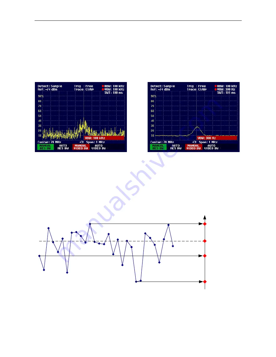
The Figs. below show a weak sine signal. In the first Fig., it is measured with a large video bandwidth
and in the second with a narrow video bandwidth.
Limiting the video bandwidth smoothes the trace considerably. This makes it much easier to determine
the level of the measured signal.
The detector comes after the video filter. The detector combines the measured spectrum so that it can
be represented as one pixel in the trace. The R&S FSH uses 301 pixels to form the trace, i.e. the whole
measured spectrum has to be represented using just 301 pixels. Common types of spectrum analyzer
detectors are the peak detector (PEAK), the sample detector (SAMPLE) and the RMS detector (RMS).
An Auto Peak detector which simultaneously displays the maximum peak and the minimum peak is
usually also provided. The Fig. below explains how these detectors work.
Maximum
Minimum
RMS
Sample
Level
深圳市盛腾仪器仪表有限公司
Tel:0755-83589391
Fax:0755-83539691
Website: www.Sengt.com


