R&S FSH
Field-Strength Measurement with Isotropic Antenna
1145.5973.12 4.141
E-14
Do the following to compensate the antenna extension
cable:
Select the TRANSD dB softkey from the Transducer
menu.
The R&S FSH will display the list of transducer factors
available in the instrument with the unit dB.
Select the appropriate transducer factor for the
antenna by using the rotary knob or cursor keys and
activate with the SELECT softkey.
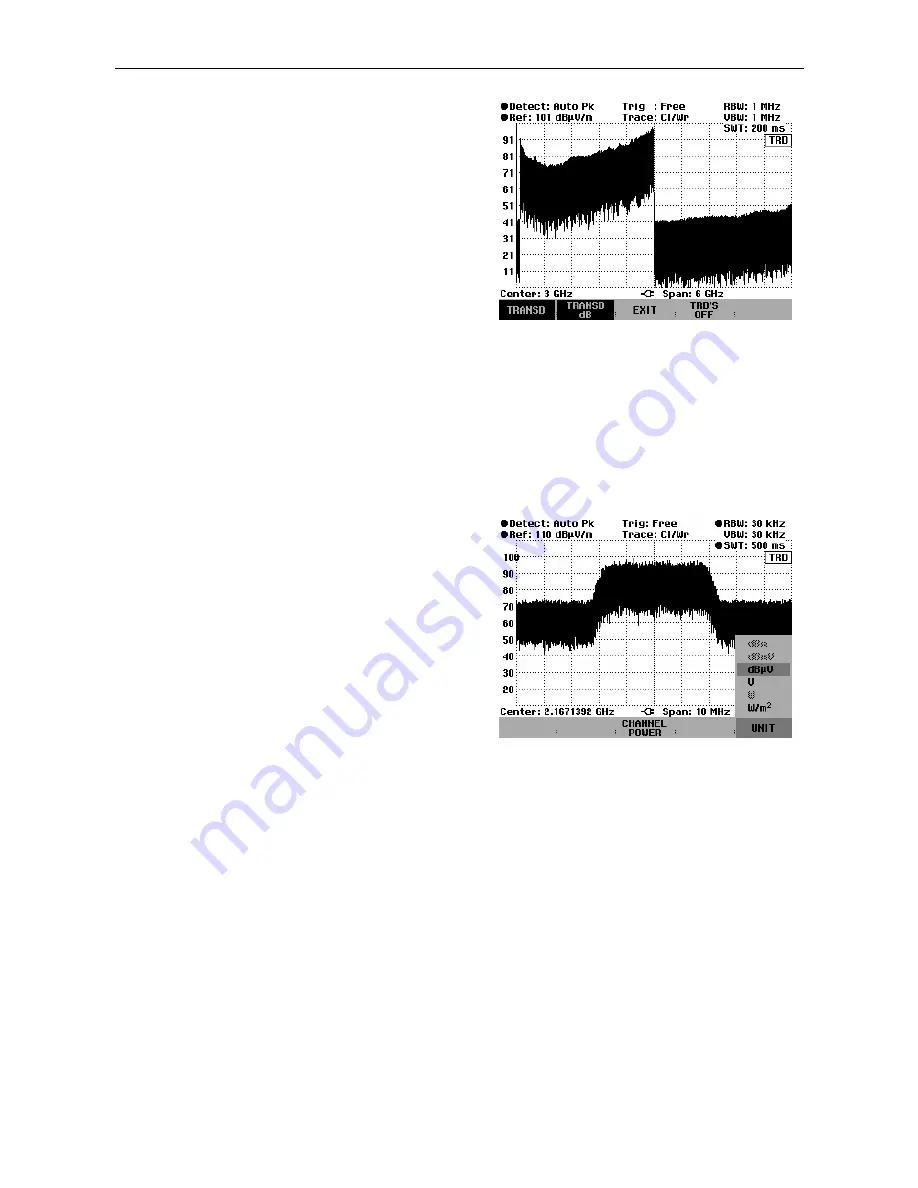
The figure at the right shows a typical trace of the
R&S TS-EMF antenna when transducer factors are
activated. The antenna is defined between 30 MHz
and 3 GHz. The R&S FSH displays the noise in this
frequency range as a frequency-dependent value that
is elevated by the antenna transducer factor. Outside
the transducer range, the R&S FSH sets the antenna
transducer factor to zero. Therefore, a measurement in
this range does not yield useful results..
To enter the display unit:
Press the UNIT softkey.
Select the unit you want by using the rotary knob or
cursor keys and confirm with the ENTER key.
The R&S FSH will display the selected unit of the
resultant field strength. If you have selected W/m
2,
the
power flux density of the resultant field strength will be
calculated and displayed.
Measurement of the resultant field strength in a transmission
channel with large bandwidth
To measure the resultant field strength in a transmission channel with large bandwidth, use the
procedure for "measuring the channel power of continuously modulated signals" described in this
chapter. Instead of the channel power, the R&S FSH will display the resultant field strength with
inclusion of the antenna factors for the isotropic antenna.
The channel power measurement function allows you to selectively measure the resultant field strength
of modulated signals by applying a high level of separation from adjacent signals. You can select the
channel bandwidth, which also includes highly broadband signals.
When measuring the channel power, the R&S FSH measures the spectrum within the channel using a
resolution bandwidth that is smaller than the channel bandwidth. It then integrates the measurement
values of the trace for channel power. This procedure is repeated for each receive direction (x, y, z) of
the isotropic antenna. The total power is determined from the three different channel powers, and it is
then converted to the resultant field strength. In this process, the R&S FSH compensates the behavior
of the type of display selected (linear or logarithmic), of the selected detected and of the resolution
深圳市盛腾仪器仪表有限公司
Tel:0755-83589391
Fax:0755-83539691
Website: www.Sengt.com


