PT113
Instruction Manual
29
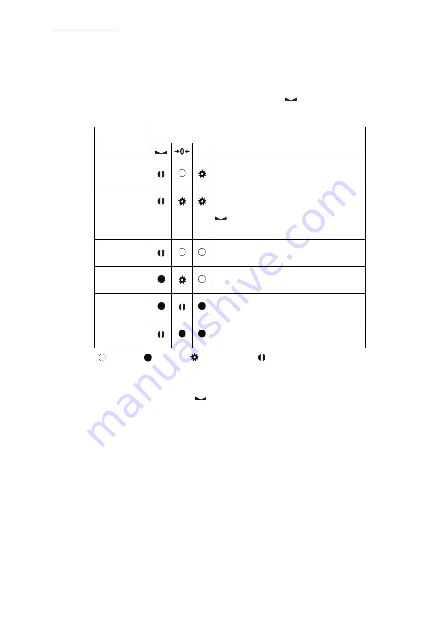
7.2 DIAGNOSTIC TESTS
RC-232C and RS-485 serial interface tests and load cell signal analogue digital conversion &
processing tests are performed sequentially in this test menu.
To enter the diagnostic test mode, press the programming switch (through the small hole at the bottom
of the panel) before power on and release the switch after powering on the PT113. The instrument will
go in to the RS-232C RXD test mode which is indicated by the lit
LED and flashing Err LED as
seen below. The status of LEDs on the front panel indicates test steps and the test result as described
below. You can go to the next test by pressing the programming switch.
Test
LED’s Status
Description
Err
RS-232C RxD
LED blanks for 0.3 sec after receiving
any data. Press the programming switch to
go to the next test.
RS-232C TxD
‘A’ to ‘Z’ characters are sent sequentially at a
0.8s interval. If the RxD and TxD pins are
shorted and the same data is received, the
LED blanks for 0.3 sec. Press the
programming switch to go to the following
test.
RS-485 RD
LED blanks for 0.3 sec after receiving
any data. Press the programming switch to
go to the following test.
RS-485 TD
‘A’ to ‘Z’ characters are sent sequentially at a
0.8 sec interval. Press the programming
switch to go the following test.
Load cell
signal
LED blanks while the load cell signal
increases. Press programming switch to go
to the following test.
LED blanks while the load cell signal
decreases. Press programming switch to go
back to the RS-232C RxD test.
LED off LED on
LED Flashing LED Blanks for 0.3 second
Table 5.6 - Diagnostic Tests
If you short circuit the RXD and TXD pins of the instrument’s RS-232C port and go in to the TxD test,
the receiving data, announced by the
LED, indicates the instrument’s interface pins have
functionality.
Press the programming switch for 5 seconds to exit the diagnostic test mode and go to back to the
operating mode.


