


SECTION 04: EXHAUST AND AFTERTREATMENT SYSTEM
PA1593
7
Release tension from drive belt (Refer to
paragraph 12.1 and 15.1 in Section 05:
Cooling System).
Cut cable ties and disconnect electrical
connector from fan clutch. Remove fan drive
shaft fasteners at the gear box.
Remove radiator fan drive mechanism
support.
Safely support catalytic converter from the
top.
Disconnect catalytic converter outlet NOx
sensor.
Remove clamps holding catalytic converter
then lower.
Remove or disconnect any piece of
equipment or component that might be in
the way or that might prevent removing the
catalytic converter.
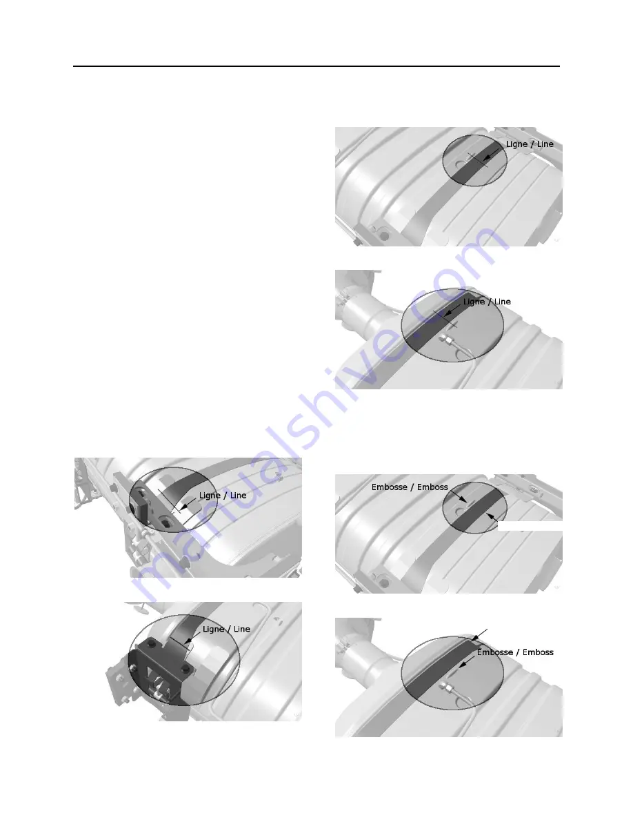
3.2 ASSEMBLING CATALYTIC CONVERTER
Before removing
Mark, with a vertical line the angular position
of the lower (both sides) and upper clamps
with regard to the clamps support located on
the catalytic converter.
Lower
Upper
Mark, with a vertical line the central position
of the lower and upper clamps with regard to
the emboss located at the bottom and at the
top of the catalytic converter.
Lower
Upper
Assembling
Position the upper clamps above the upper
emboss and the lower clamps below the
lower emboss of the catalytic converter.
Lower
Upper
CLAMP
CLAMP
CLAMP
Содержание X3-45 2016
Страница 4: ......
Страница 16: ...Section 00 GENERAL INFORMATION PA1593 12 FIGURE 12 METRIC US STANDARD CONVERSION TABLE 00005...
Страница 17: ...Section 00 GENERAL INFORMATION 13 PA1593 FIGURE 13 CONVERSION CHART 00006...
Страница 18: ......
Страница 26: ......
Страница 58: ......
Страница 72: ...Section 04 EXHAUST AND AFTERTREATMENT SYSTEM PA1593 14 7 TORQUE SPECIFICATIONS...
Страница 73: ...SECTION 04 EXHAUST AND AFTERTREATMENT SYSTEM PA1593 15...
Страница 74: ...Section 04 EXHAUST AND AFTERTREATMENT SYSTEM PA1593 16...
Страница 76: ......
Страница 96: ......
Страница 134: ......
Страница 176: ...SECTION 06B ELECTRICAL 38 overcurrent working Circuit 306 shorted to ground...
Страница 180: ......
Страница 202: ......
Страница 205: ...Section 09 PROPELLER SHAFT PA1593 3 FIGURE 1 PROPELLER SHAFT ASSEMBLY 09002...
Страница 256: ......
Страница 268: ......
Страница 295: ...SECTION 16 SUSPENSION PA1593 9 2 5 TORQUE SPECIFICATIONS...
Страница 296: ...Section 16 SUSPENSION PA1593 10...
Страница 297: ...Section 16 SUSPENSION PA1593 11...
Страница 314: ......
Страница 364: ...Section 18 BODY PA1593 50 6 8 BODY PANEL AND WINDOW SPACING FIGURE 45 BODY PANEL AND WINDOW SPACING TYPICAL 18631...
Страница 380: ......
Страница 388: ......
Страница 413: ...Section 22 HEATING AND AIR CONDITIONING PA1593 15 FIGURE 18 REFRIGERANT CIRCUIT CENTRAL SYSTEM...
Страница 433: ...Section 22 HEATING AND AIR CONDITIONING PA1593 35 FIGURE 36 CENTRAL HEATING SYSTEM COMPONENTS...