


Section 06: ELECTRICAL
PA1593
20
SEQUENCE and press ENTER button to
initiate the test mode for electrical motors;
3. Ten (10)
beeps
can be heard indicating the
motor test mode has started.
Using the test mode:
During the entire test, the instrument panel
audible alarm gives a signal each second to
remind that the motor test mode is underway.
4.4.1 Test
Sequence
Go to the condenser compartment:
The condenser fans start at speed 1, then
after a short pause, speed 2 activates.
The passenger's unit refrigerant solenoid
valve activates.
Then 5 beeps can be heard from the back-up
alarm to indicate to go to the engine
compartment.
In the engine compartment, the sequence is
as follows:
Toilet fan motor starts.
A/C compressor clutch activates 3 times.
Left compressor unloader activates 3 times.
Right compressor unloader activates 3
times.
Fan clutch is disengaged (fan can be turned
freely by hand).
Fan clutch engages in speed 1 (fan can be
turned by hand but with a certain
resistance).
Fan clutch engages in speed 2 (cannot be
turned but hand).
5 beeps from the back-up alarm indicate to go to
the evaporator compartment.
In the evaporator compartment:
Evaporator fan motor runs at speed 1 for 3
seconds then runs at speed 2 for 2 seconds.
Hot water pump starts running for 5 seconds
and hot water pneumatic valve cycles 3
times.
5 beeps from the back-up alarm indicate to get
to the driver’s area inside the vehicle.
Inside the vehicle:
The driver's HVAC unit refrigerant solenoid
valve cycles 3 times and the hot water
pneumatic valve cycles 3 times also.
To exit the electric motors test sequence,
press ESCAPE button, select STOP TEST
submenu and then press ENTER button
twice.
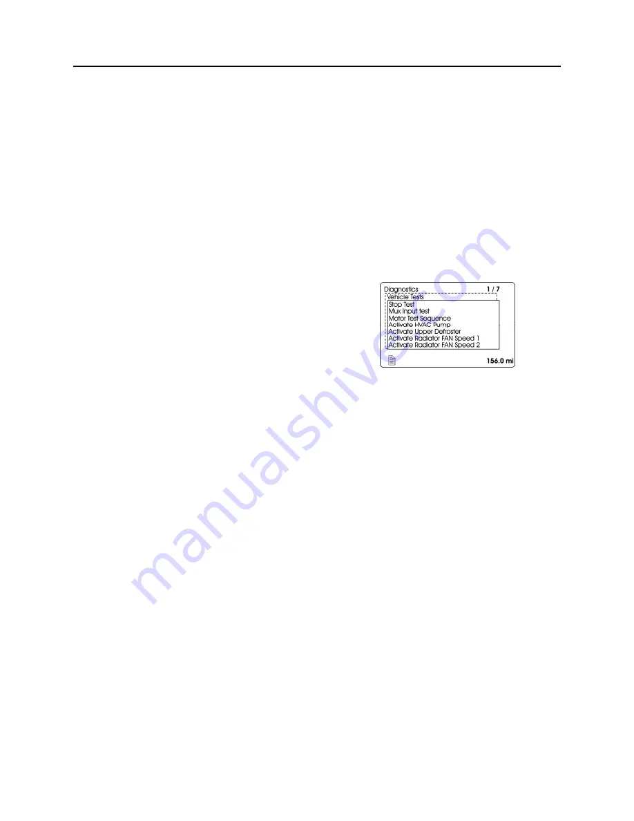
4.5 FORCED ACTIVATION OF THE
RADIATOR FAN CLUTCH
To prevent the engine from overheating in case
of malfunction of the clutch activation system, it
is possible to force activation of the clutch.
1. On the Driver Information Display, select
DIAGNOSTICS menu. Select VEHICLE
TESTS submenu and then ACTIVATE
RADIATOR FAN SPEED 1 or ACTIVATE
RADIATOR FAN SPEED 2 as required.
2. The DID status line will show TEST to
confirm the forced activation of the radiator
fan clutch. To cancel, turn the ignition
switch to the OFF position or press
ESCAPE button, select STOP TEST
submenu and then press ENTER button
twice. TEST will disappear from the DID
status line.
If the fan clutch does not engage using this
procedure then the clutch is faulty or the wiring
between the multiplex module and the clutch is
faulty. Mechanically lock the fan clutch as
described in section 05: COOLING
SYSTEM of
the maintenance manual.
Содержание X3-45 2016
Страница 4: ......
Страница 16: ...Section 00 GENERAL INFORMATION PA1593 12 FIGURE 12 METRIC US STANDARD CONVERSION TABLE 00005...
Страница 17: ...Section 00 GENERAL INFORMATION 13 PA1593 FIGURE 13 CONVERSION CHART 00006...
Страница 18: ......
Страница 26: ......
Страница 58: ......
Страница 72: ...Section 04 EXHAUST AND AFTERTREATMENT SYSTEM PA1593 14 7 TORQUE SPECIFICATIONS...
Страница 73: ...SECTION 04 EXHAUST AND AFTERTREATMENT SYSTEM PA1593 15...
Страница 74: ...Section 04 EXHAUST AND AFTERTREATMENT SYSTEM PA1593 16...
Страница 76: ......
Страница 96: ......
Страница 134: ......
Страница 176: ...SECTION 06B ELECTRICAL 38 overcurrent working Circuit 306 shorted to ground...
Страница 180: ......
Страница 202: ......
Страница 205: ...Section 09 PROPELLER SHAFT PA1593 3 FIGURE 1 PROPELLER SHAFT ASSEMBLY 09002...
Страница 256: ......
Страница 268: ......
Страница 295: ...SECTION 16 SUSPENSION PA1593 9 2 5 TORQUE SPECIFICATIONS...
Страница 296: ...Section 16 SUSPENSION PA1593 10...
Страница 297: ...Section 16 SUSPENSION PA1593 11...
Страница 314: ......
Страница 364: ...Section 18 BODY PA1593 50 6 8 BODY PANEL AND WINDOW SPACING FIGURE 45 BODY PANEL AND WINDOW SPACING TYPICAL 18631...
Страница 380: ......
Страница 388: ......
Страница 413: ...Section 22 HEATING AND AIR CONDITIONING PA1593 15 FIGURE 18 REFRIGERANT CIRCUIT CENTRAL SYSTEM...
Страница 433: ...Section 22 HEATING AND AIR CONDITIONING PA1593 35 FIGURE 36 CENTRAL HEATING SYSTEM COMPONENTS...