


Section 12: BRAKE AND AIR SYSTEM
10
X3-45 Commuter PA1593 DOB 2400-2489
Section 12 Updated Sept. 2015
supplied in the applicable booklet annexed at the
end of this section.
Item Description
Notes
1
Air Compressor
Wabco 636
2
O’Ring
3
Stud (3)
M12
4
Flange Nut (3)
Torque to 15lb-ft (20 Nm)
5
Nipple (2)
6
Hose Assembly
11.1
COMPRESSOR REMOVAL AND
INSTALLATION
1. Exhaust compressed air from air system by
opening the drain valve of each air tank.
2. Drain the engine cooling system. See
Section 5: "
Cooling System
".
3. Access the compressor by the engine R.H.
side compartment. Identify and disconnect
all air, coolant and oil lines from the
compressor assembly.
4. Remove the three compressor flange
mounting nuts.
5. Slide air compressor rearward to disengage
the hub from coupling. Remove the air
compressor.
Remove and retain the oil supply tube that
runs between the compressor and the engine
Reverse removal procedure for installation.
12. EMERGENCY/PARKING BRAKE
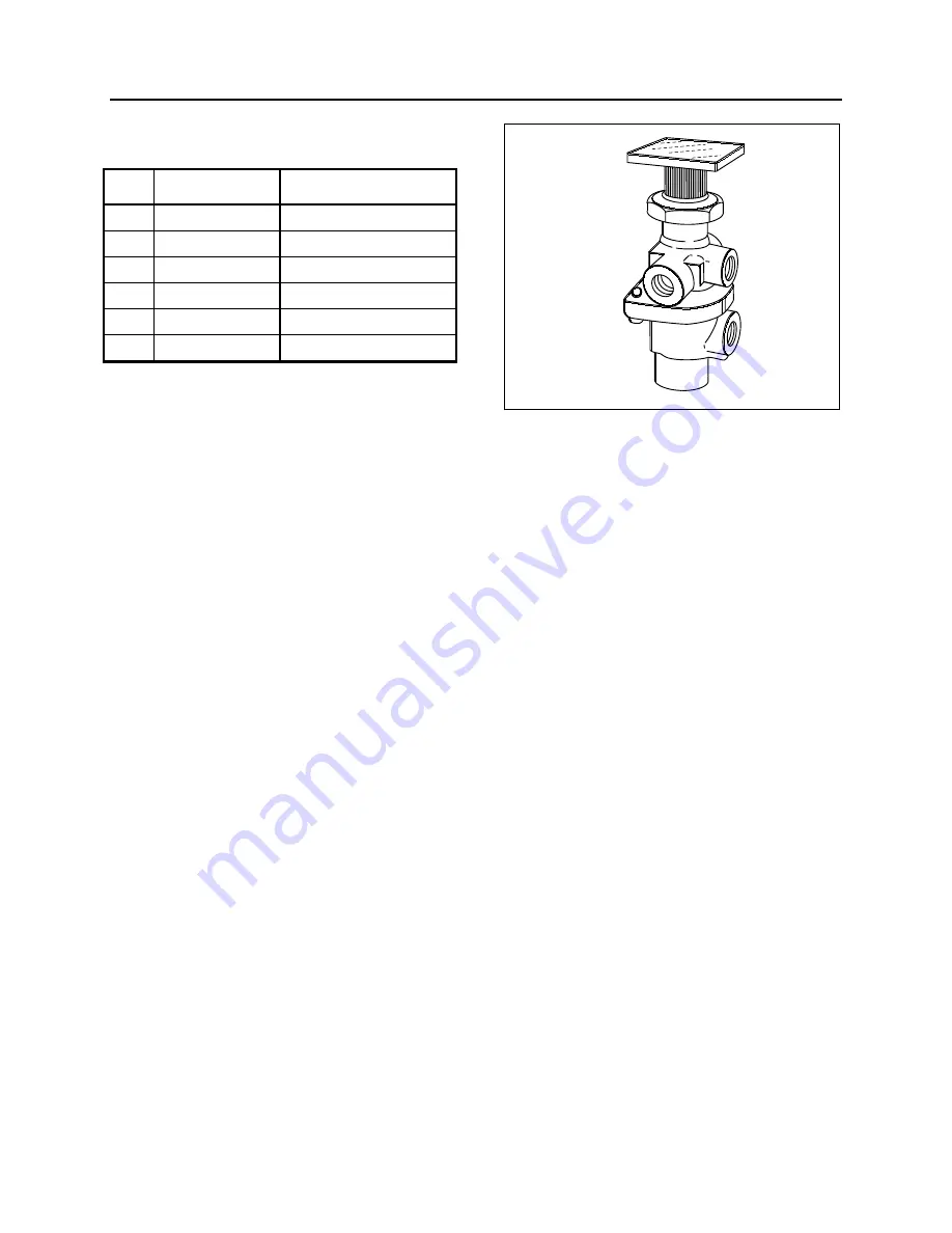
CONTROL VALVE (PP-1)
A push-pull control valve mounted on the L.H.
lateral console is provided for parking brake
application or release. The spring brakes are
self-actuated whenever the control valve supply
pressure drops below 60 psi (414 kPa). In the
UP position, brakes are ON. In the DOWN
position, brakes are RELEASED. A protective
case around the knob prevents accidentally
releasing the brakes.
FIGURE 10: PP-1
12142
Maintenance and repair information on this valve
is supplied in the applicable booklet annexed to
this section under reference number
SD-03-3611.
Remove the valve the following way:
1. Drain the air system.
2. Access this valve by tearing out the finishing
panel, which holds the controls in place
(Fig. 10).
3. Disconnect the air tubes.
4. Remove the retaining screws.
5. Service or replace the valve.
6. Installation is the reverse of removal.
13. EMERGENCY / PARKING BRAKES
OVERRULE CONTROL VALVE (RD-3)
A RD-3 control valve is used with the parking
brake overrule system. In the case of self-
application of spring brakes due to a pressure
drop, the brakes can be released by holding
down this control valve. Maintenance and repair
information on this valve is supplied in the
applicable booklet annexed to this section under
reference number SD-03-3611.
Содержание X3-45 2016
Страница 4: ......
Страница 16: ...Section 00 GENERAL INFORMATION PA1593 12 FIGURE 12 METRIC US STANDARD CONVERSION TABLE 00005...
Страница 17: ...Section 00 GENERAL INFORMATION 13 PA1593 FIGURE 13 CONVERSION CHART 00006...
Страница 18: ......
Страница 26: ......
Страница 58: ......
Страница 72: ...Section 04 EXHAUST AND AFTERTREATMENT SYSTEM PA1593 14 7 TORQUE SPECIFICATIONS...
Страница 73: ...SECTION 04 EXHAUST AND AFTERTREATMENT SYSTEM PA1593 15...
Страница 74: ...Section 04 EXHAUST AND AFTERTREATMENT SYSTEM PA1593 16...
Страница 76: ......
Страница 96: ......
Страница 134: ......
Страница 176: ...SECTION 06B ELECTRICAL 38 overcurrent working Circuit 306 shorted to ground...
Страница 180: ......
Страница 202: ......
Страница 205: ...Section 09 PROPELLER SHAFT PA1593 3 FIGURE 1 PROPELLER SHAFT ASSEMBLY 09002...
Страница 256: ......
Страница 268: ......
Страница 295: ...SECTION 16 SUSPENSION PA1593 9 2 5 TORQUE SPECIFICATIONS...
Страница 296: ...Section 16 SUSPENSION PA1593 10...
Страница 297: ...Section 16 SUSPENSION PA1593 11...
Страница 314: ......
Страница 364: ...Section 18 BODY PA1593 50 6 8 BODY PANEL AND WINDOW SPACING FIGURE 45 BODY PANEL AND WINDOW SPACING TYPICAL 18631...
Страница 380: ......
Страница 388: ......
Страница 413: ...Section 22 HEATING AND AIR CONDITIONING PA1593 15 FIGURE 18 REFRIGERANT CIRCUIT CENTRAL SYSTEM...
Страница 433: ...Section 22 HEATING AND AIR CONDITIONING PA1593 35 FIGURE 36 CENTRAL HEATING SYSTEM COMPONENTS...