


Section 03: FUEL SYSTEM
PA1593
12
With the ignition "ON" and the proper diagnostic
tool (DDR) (for information regarding the DDR,
see
"01 ENGINE"
in this manual), check the
throttle counts at idle and full throttle positions.
Proper pedal output should be 20/30 counts at
idle and 200/235 at full throttle. If adjustment is
necessary, remove the potentiometer retaining
screws and rotate the potentiometer clockwise
to increase counts or counterclockwise to
decrease. When correct output is confirmed,
tighten retaining screws.
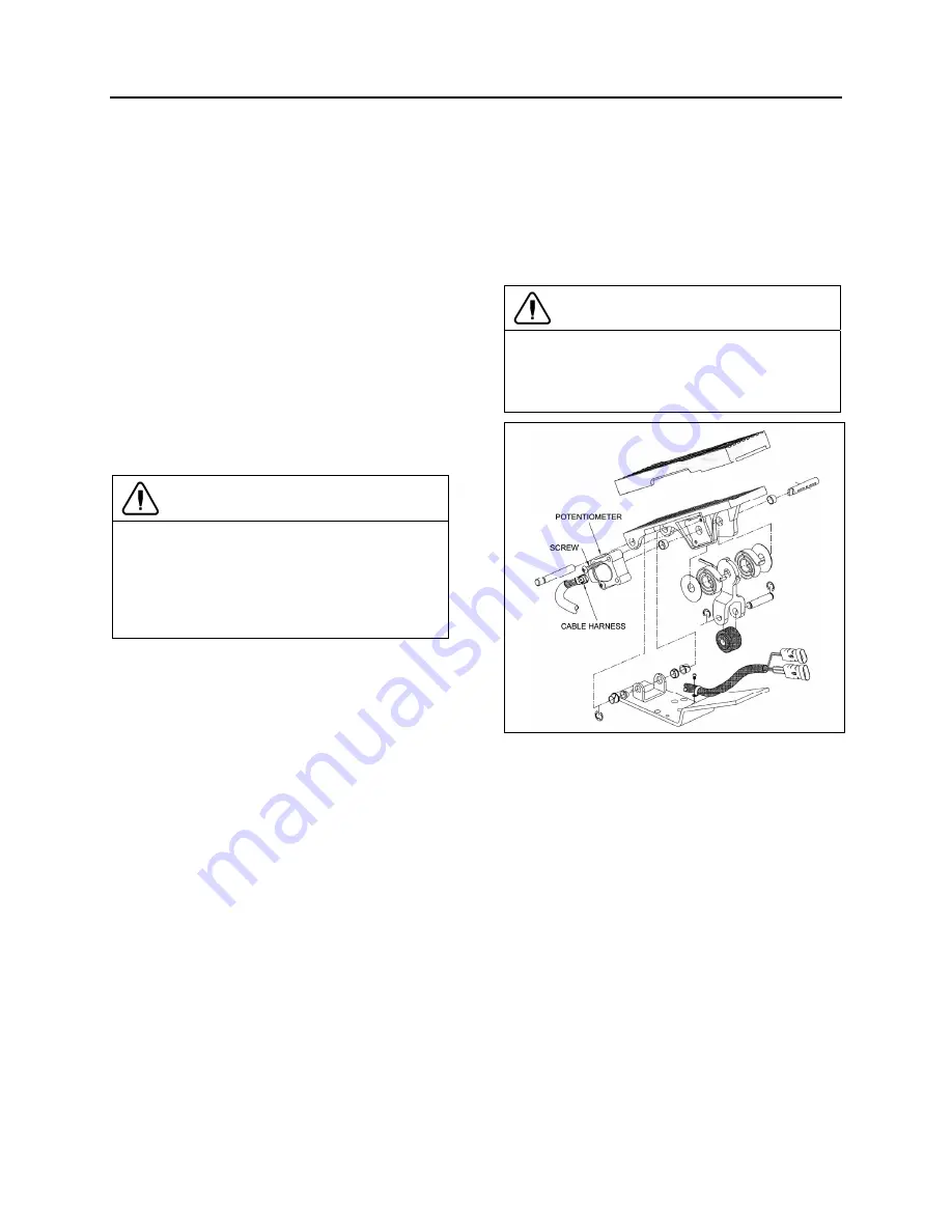
6.2 POTENTIOMETER REPLACEMENT
1. Disconnect cable harness connector.
2.
Loosen the two screws and remove
potentiometer. Retain for re-assembly.
3. Discard potentiometer (Fig. 11).
CAUTION
Note the routing and clamping locations of the
cable before disassembly. Proper cable
routing and fastening is critical to the
operation of this system. Marking the foot
pedal assembly to record cable routing is
recommended.
2.
Position new potentiometer. Press
potentiometer onto the potentiometer shaft,
matching cutouts in shaft to drive tangs of
potentiometer. Apply hand pressure until
potentiometer has bottomed out in housing.
Reinstall screws (Fig. 11) and tighten just
enough to secure potentiometer lightly. Tighten
screws to 10 - 20 Lbf-in (1.13 - 2.26 Nm).
3. Reconnect electronic foot pedal assembly's
cable harness to the ECM connector. If
potentiometer calibration is necessary (see
"FUEL PEDAL ADJUSTMENT"
in this
section).
CAUTION
Make sure the cable harness is routed
correctly, and securely installed so that it does
not become pinched, stretched, or otherwise
damaged during vehicle operation.
FIGURE 11: ELECTRONIC FOOT PEDAL ASSEMBLY
03035
7. SPECIFICATIONS
Primary Fuel Filter (Fuel/Water Separator) With Volvo D13 Engine
Part number ............................................................................................................................................21380475
Filter torque ............................................................................................................. ½-¾ turn after gasket contact
Secondary Fuel Filter With Volvo D13 Engine
Part number ............................................................................................................................................20972293
Filter torque ............................................................................................................. ¾- 1 turn after gasket contact
Fuel tank Capacity
Standard (All vehicles) ................................................................................................ 208 US gallons (787 liters)
Air Cleaner
Service Part No ........................................................................................................................................ 7182 8N
Prevost number (element cartridge) .......................................................................................................... 530197
Содержание X3-45 2016
Страница 4: ......
Страница 16: ...Section 00 GENERAL INFORMATION PA1593 12 FIGURE 12 METRIC US STANDARD CONVERSION TABLE 00005...
Страница 17: ...Section 00 GENERAL INFORMATION 13 PA1593 FIGURE 13 CONVERSION CHART 00006...
Страница 18: ......
Страница 26: ......
Страница 58: ......
Страница 72: ...Section 04 EXHAUST AND AFTERTREATMENT SYSTEM PA1593 14 7 TORQUE SPECIFICATIONS...
Страница 73: ...SECTION 04 EXHAUST AND AFTERTREATMENT SYSTEM PA1593 15...
Страница 74: ...Section 04 EXHAUST AND AFTERTREATMENT SYSTEM PA1593 16...
Страница 76: ......
Страница 96: ......
Страница 134: ......
Страница 176: ...SECTION 06B ELECTRICAL 38 overcurrent working Circuit 306 shorted to ground...
Страница 180: ......
Страница 202: ......
Страница 205: ...Section 09 PROPELLER SHAFT PA1593 3 FIGURE 1 PROPELLER SHAFT ASSEMBLY 09002...
Страница 256: ......
Страница 268: ......
Страница 295: ...SECTION 16 SUSPENSION PA1593 9 2 5 TORQUE SPECIFICATIONS...
Страница 296: ...Section 16 SUSPENSION PA1593 10...
Страница 297: ...Section 16 SUSPENSION PA1593 11...
Страница 314: ......
Страница 364: ...Section 18 BODY PA1593 50 6 8 BODY PANEL AND WINDOW SPACING FIGURE 45 BODY PANEL AND WINDOW SPACING TYPICAL 18631...
Страница 380: ......
Страница 388: ......
Страница 413: ...Section 22 HEATING AND AIR CONDITIONING PA1593 15 FIGURE 18 REFRIGERANT CIRCUIT CENTRAL SYSTEM...
Страница 433: ...Section 22 HEATING AND AIR CONDITIONING PA1593 35 FIGURE 36 CENTRAL HEATING SYSTEM COMPONENTS...