


Section 22: HEATING AND AIR CONDITIONING
PA1593
4
1. HEATING AND AIR CONDITIONING
The interior of the vehicle is pressurized by its
Heating, Ventilation, Air Conditioning (HVAC)
system. The vehicle is equipped with a Central
HVAC System; air flow and controls divide the
vehicle in two areas: driver’s area and
passengers’ area. The interior of the vehicle
should always be slightly pressurized to prevent
dust and moisture from entering vehicle. Each
section has its own fresh air, returning air and
discharge air ducting. The exhaust is mainly
done through the rear ventilator and through
normal air-tightness losses.
2. AIR CIRCULATION WITH CENTRAL
HVAC SYSTEM
2.1 DRIVER’S
AREA
Fresh air is taken from a plenum underneath the
front service compartment and enters the mixing
box through an ON/OFF damper. Return air is
taken through the base of the dashboard panel
utility compartments into the mixing box. Mixed
air goes through cooling and heating coils, fans
and discharge ducts.
Both right and left discharge ducts defrost one
half of the windshield. The driver can also divert
some air flow to the console, from which he can
direct air to his knees and/or upper body with
adjustable HVAC air registers and to his feet
with the appropriate button (see Fig. 1 and
Operator’s manual).
FIGURE 1: DRIVER’S AIR CIRCULATION
22307
X3-45 coaches are also equipped with a
windshield upper section de-icing system. Also,
one additional air register is located in the
driver’s area but supplied by the passengers’ air
ducting system. It is installed in the stepwell for
step de-icing.
2.2 PASSENGERS’
AREA
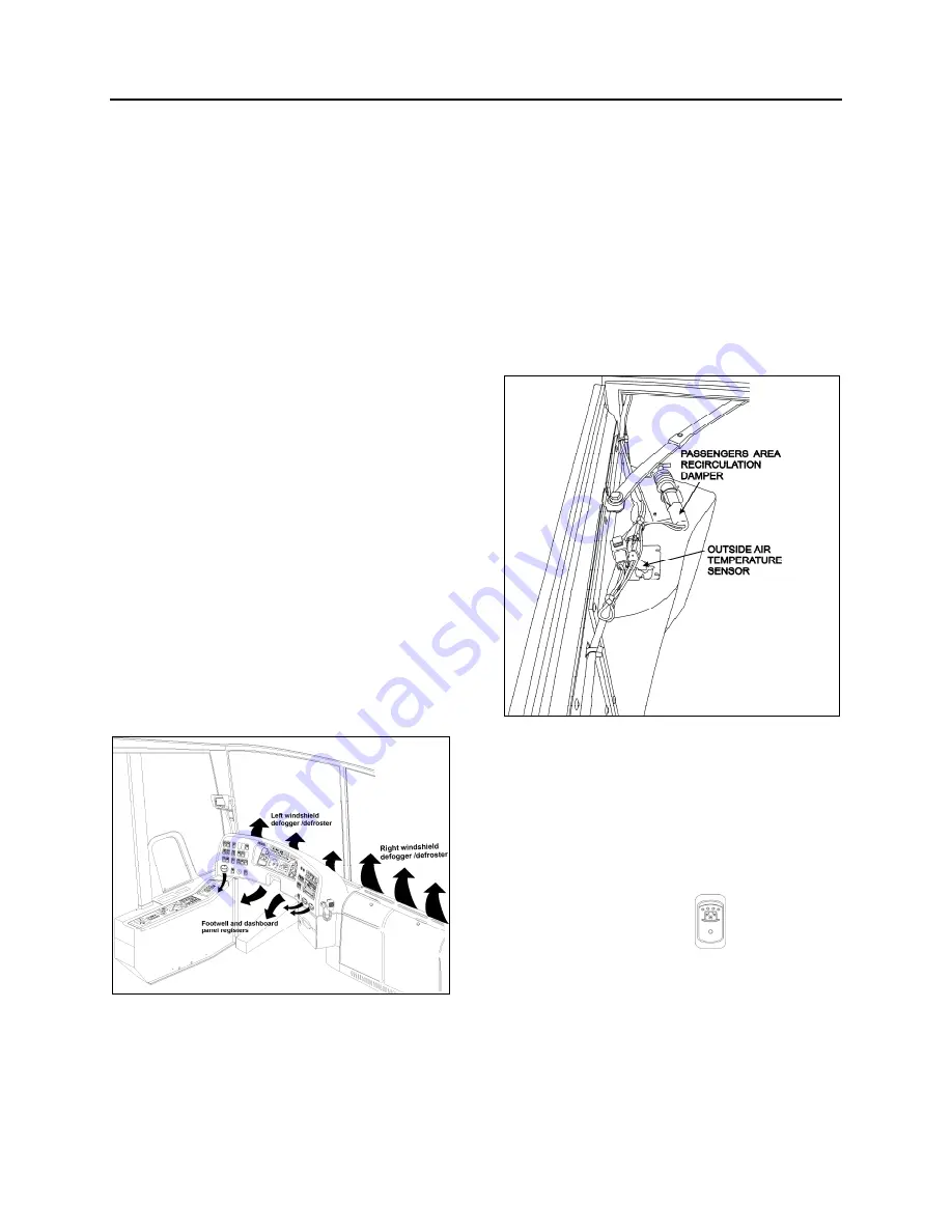
Fresh air enters the vehicle on the L.H. side,
through the recirculation damper located inside
the evaporator compartment door (Fig. 2). The
damper can be fully opened for normal operation
or closed for extreme weather or highly polluted
areas (Refer to the Operator's Manual for more
details). The recirculation REC button is located
on the HVAC control unit. Press down the button
to partially close the fresh air damper. Return air
is drawn from inside the vehicle through the
register duct located on L.H. side of vehicle (Fig.
3).
FIGURE 2: PASSENGERS' AREA RECIRCULATION
DAMPER
22302
A double blower fan unit, which is activated by the
evaporator motor, draws mixed air through an air
filter, cooling and heating coils, then forces this air
in the ventilation ducts along the walls, and finally
exhausts it just below side windows.
X3-45 coaches are also equipped with an
overhead compartment ventilation system, a
three-position rocker switch
(0FF - 1
st
speed
- 2
nd
speed) located on R.H. dashboard panel
controls the speed of both fans. Return air is
drawn just below the middle side windows
through an air filter into the overhead
compartment fan; discharge air is fed to the
rotating registers through the ventilation duct (Fig.
4).
Содержание X3-45 2016
Страница 4: ......
Страница 16: ...Section 00 GENERAL INFORMATION PA1593 12 FIGURE 12 METRIC US STANDARD CONVERSION TABLE 00005...
Страница 17: ...Section 00 GENERAL INFORMATION 13 PA1593 FIGURE 13 CONVERSION CHART 00006...
Страница 18: ......
Страница 26: ......
Страница 58: ......
Страница 72: ...Section 04 EXHAUST AND AFTERTREATMENT SYSTEM PA1593 14 7 TORQUE SPECIFICATIONS...
Страница 73: ...SECTION 04 EXHAUST AND AFTERTREATMENT SYSTEM PA1593 15...
Страница 74: ...Section 04 EXHAUST AND AFTERTREATMENT SYSTEM PA1593 16...
Страница 76: ......
Страница 96: ......
Страница 134: ......
Страница 176: ...SECTION 06B ELECTRICAL 38 overcurrent working Circuit 306 shorted to ground...
Страница 180: ......
Страница 202: ......
Страница 205: ...Section 09 PROPELLER SHAFT PA1593 3 FIGURE 1 PROPELLER SHAFT ASSEMBLY 09002...
Страница 256: ......
Страница 268: ......
Страница 295: ...SECTION 16 SUSPENSION PA1593 9 2 5 TORQUE SPECIFICATIONS...
Страница 296: ...Section 16 SUSPENSION PA1593 10...
Страница 297: ...Section 16 SUSPENSION PA1593 11...
Страница 314: ......
Страница 364: ...Section 18 BODY PA1593 50 6 8 BODY PANEL AND WINDOW SPACING FIGURE 45 BODY PANEL AND WINDOW SPACING TYPICAL 18631...
Страница 380: ......
Страница 388: ......
Страница 413: ...Section 22 HEATING AND AIR CONDITIONING PA1593 15 FIGURE 18 REFRIGERANT CIRCUIT CENTRAL SYSTEM...
Страница 433: ...Section 22 HEATING AND AIR CONDITIONING PA1593 35 FIGURE 36 CENTRAL HEATING SYSTEM COMPONENTS...