


Section 18: BODY
PA1593
16
remove the two bolts on each bumper side to
separate the bumper from the compartment
door. To install bumper, reverse the removal
procedure.
WARNING
Front bumper is heavy. Use proper lifting
equipment to support the bumper during the
removal and installation operations to avoid
personal injury.
FIGURE 9: FRONT BUMPER RELEASE HANDLE
18613
FIGURE 10: FRONT BUMPER COMPARTMENT
18614
FIGURE 11: FRONT BUMPER REMOVAL
18565
6.1.2 Headlights
Refer to Paragraph Headlights, included in
Section 06: Electrical of the Maintenance
Manual for complete information on headlights.
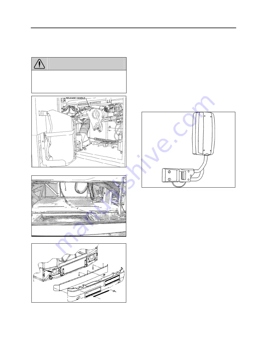
6.1.3 Rear View Mirrors (Rosco)
Your vehicle is equipped with two Rosco exterior
mirrors.
The mirrors can easily be adjusted by using the
remote controls located on the L.H. side control
panel. The mirrors have easy to replace glass in
case of breakage. Remote control motors can
also be replaced.
FIGURE 12: REAR VIEW MIRROR (ROSCO)
18398A
Adjustment
At the base of the mirror arm, loosen the
mounting bolt to swing arm in or out.
To pivot the mirror head, loosen the setscrews
on each side of the ball stub at the base of the
mirror head to facilitate the adjustment.
Disassembly
At end of mirror arm, loosen the setscrews to
relieve tension on the ball stem. Remove the ball
stem from the arm.
Remove the four screws fastening the mirror
arm base to the coach.
Assembly
Mount the mirror arm base to the coach. Insert
the ball stem into the mirror arm and tighten the
socket setscrews.
Содержание X3-45 2016
Страница 4: ......
Страница 16: ...Section 00 GENERAL INFORMATION PA1593 12 FIGURE 12 METRIC US STANDARD CONVERSION TABLE 00005...
Страница 17: ...Section 00 GENERAL INFORMATION 13 PA1593 FIGURE 13 CONVERSION CHART 00006...
Страница 18: ......
Страница 26: ......
Страница 58: ......
Страница 72: ...Section 04 EXHAUST AND AFTERTREATMENT SYSTEM PA1593 14 7 TORQUE SPECIFICATIONS...
Страница 73: ...SECTION 04 EXHAUST AND AFTERTREATMENT SYSTEM PA1593 15...
Страница 74: ...Section 04 EXHAUST AND AFTERTREATMENT SYSTEM PA1593 16...
Страница 76: ......
Страница 96: ......
Страница 134: ......
Страница 176: ...SECTION 06B ELECTRICAL 38 overcurrent working Circuit 306 shorted to ground...
Страница 180: ......
Страница 202: ......
Страница 205: ...Section 09 PROPELLER SHAFT PA1593 3 FIGURE 1 PROPELLER SHAFT ASSEMBLY 09002...
Страница 256: ......
Страница 268: ......
Страница 295: ...SECTION 16 SUSPENSION PA1593 9 2 5 TORQUE SPECIFICATIONS...
Страница 296: ...Section 16 SUSPENSION PA1593 10...
Страница 297: ...Section 16 SUSPENSION PA1593 11...
Страница 314: ......
Страница 364: ...Section 18 BODY PA1593 50 6 8 BODY PANEL AND WINDOW SPACING FIGURE 45 BODY PANEL AND WINDOW SPACING TYPICAL 18631...
Страница 380: ......
Страница 388: ......
Страница 413: ...Section 22 HEATING AND AIR CONDITIONING PA1593 15 FIGURE 18 REFRIGERANT CIRCUIT CENTRAL SYSTEM...
Страница 433: ...Section 22 HEATING AND AIR CONDITIONING PA1593 35 FIGURE 36 CENTRAL HEATING SYSTEM COMPONENTS...