


Section 14: STEERING
Section 14 Updated Oct.2014
X3-45 Commuter PA1593 DOB 2400-2489
3
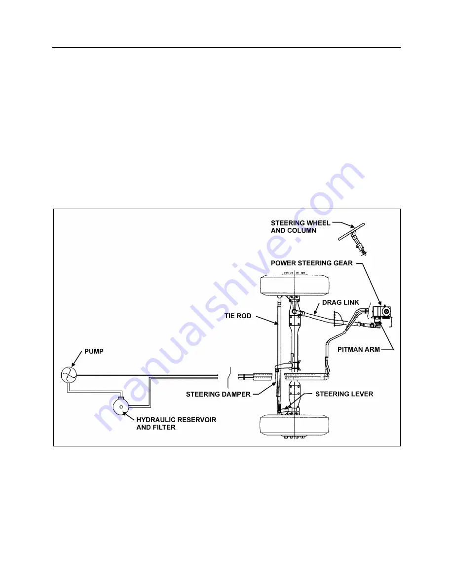
1. STEERING SYSTEM DESCRIPTION
The steering system consists of the steering
wheel and column assembly, a vane-type
hydraulic pump, reservoir, filter, interconnecting
system lines and hoses, integral power steering
gear, linkage and steering damper (Fig. 1). The
steering linkage includes the pitman arm, drag
link, steering arm, tie rod arms and tie rod.
Hydraulic components are added to transmit,
increase and regulate steering control forces.
These elements are:
1. Steering stabilizer (damper);
2. A vane type hydraulic pump; and
3. Hydraulic reservoir and hoses.
The steering stabilizer reduces road shocks and
vibrations in the system. The steering gearbox is
self powered and provides movement with power
assistance to the left wheel.
Steering stability and tire wear are influenced by
wheels, hubs, tires, air suspension, brakes, front
suspension and front end alignment which are all
covered in their respective sections in this
manual.
FIGURE 1: I-BEAM AXLE STEERING SYSTEM SETUP
14041
Содержание X3-45 2016
Страница 4: ......
Страница 16: ...Section 00 GENERAL INFORMATION PA1593 12 FIGURE 12 METRIC US STANDARD CONVERSION TABLE 00005...
Страница 17: ...Section 00 GENERAL INFORMATION 13 PA1593 FIGURE 13 CONVERSION CHART 00006...
Страница 18: ......
Страница 26: ......
Страница 58: ......
Страница 72: ...Section 04 EXHAUST AND AFTERTREATMENT SYSTEM PA1593 14 7 TORQUE SPECIFICATIONS...
Страница 73: ...SECTION 04 EXHAUST AND AFTERTREATMENT SYSTEM PA1593 15...
Страница 74: ...Section 04 EXHAUST AND AFTERTREATMENT SYSTEM PA1593 16...
Страница 76: ......
Страница 96: ......
Страница 134: ......
Страница 176: ...SECTION 06B ELECTRICAL 38 overcurrent working Circuit 306 shorted to ground...
Страница 180: ......
Страница 202: ......
Страница 205: ...Section 09 PROPELLER SHAFT PA1593 3 FIGURE 1 PROPELLER SHAFT ASSEMBLY 09002...
Страница 256: ......
Страница 268: ......
Страница 295: ...SECTION 16 SUSPENSION PA1593 9 2 5 TORQUE SPECIFICATIONS...
Страница 296: ...Section 16 SUSPENSION PA1593 10...
Страница 297: ...Section 16 SUSPENSION PA1593 11...
Страница 314: ......
Страница 364: ...Section 18 BODY PA1593 50 6 8 BODY PANEL AND WINDOW SPACING FIGURE 45 BODY PANEL AND WINDOW SPACING TYPICAL 18631...
Страница 380: ......
Страница 388: ......
Страница 413: ...Section 22 HEATING AND AIR CONDITIONING PA1593 15 FIGURE 18 REFRIGERANT CIRCUIT CENTRAL SYSTEM...
Страница 433: ...Section 22 HEATING AND AIR CONDITIONING PA1593 35 FIGURE 36 CENTRAL HEATING SYSTEM COMPONENTS...