Section 10: FRONT AXLE
PA1593
8
4. Check the stroke of the steering stabilizer
cylinder (damper). It should not exceed
12.59 inches (320 mm).
5. This must be done for a full left turn.
6. If readjustment is required:
a. Remove the swivel stop screw.
b. Add to the stop screw the required
number of washers to obtain the proper
measure, tighten the stop screw
afterwards. Two washers of different
thickness are available: 1/16 inch and
3/16 inch.
NOTE
If steering angle stoppers are changed, a
special procedure is required for readjusting
gearbox steering limiter. See paragraph 6.5
‘’Hydraulic Stop’’ in this section.
6.5 HYDRAULIC
STOP
NOTE
Before steering limiter readjustment, verify
vehicle wheel alignment and ensure that oil
level is checked and that air bleeding is done.
Refer to
“ZF-Servocom Repair Manual’’
annexed
at the end of Section 14
‘’Steering’’
under
heading
‘Setting and Functional Test.
6.6
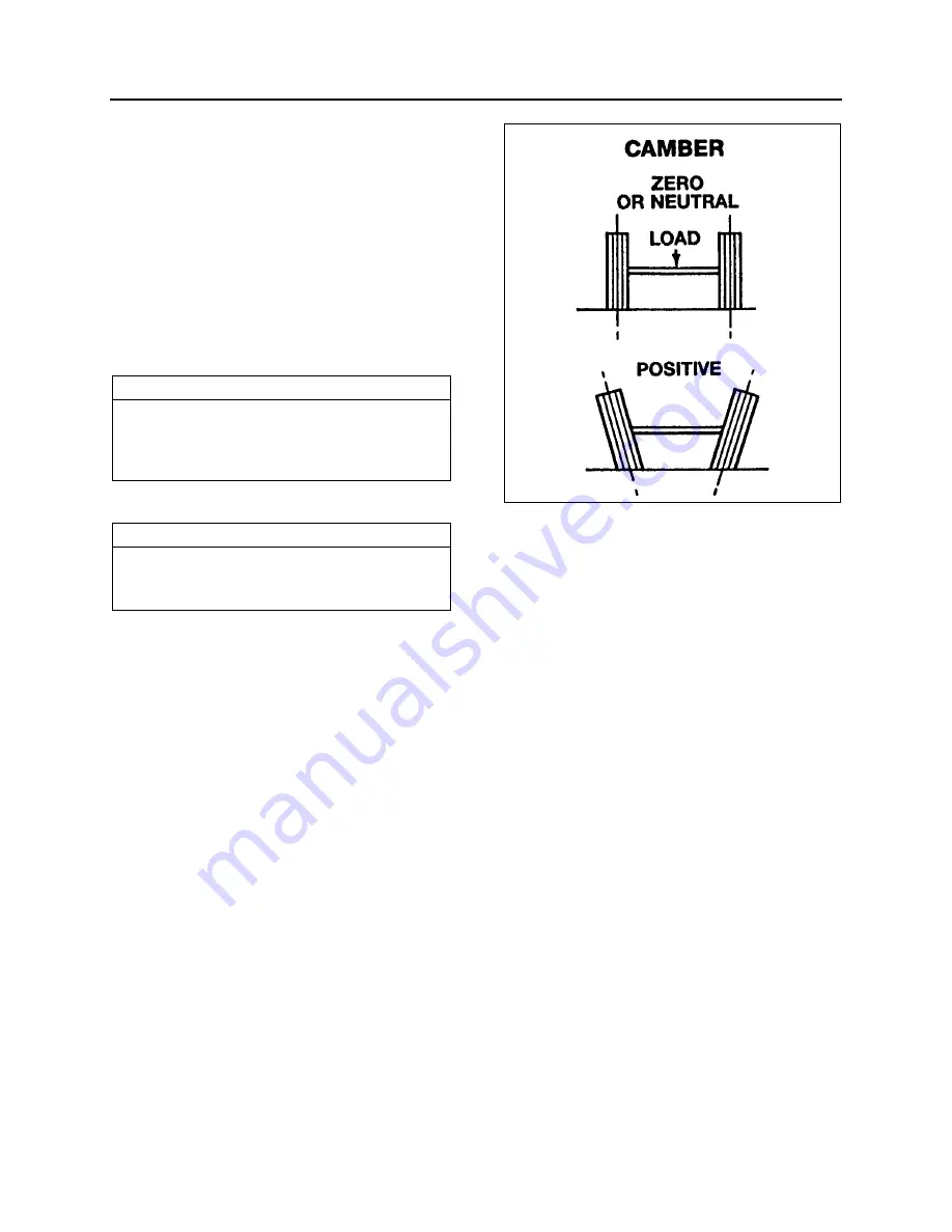
FRONT WHEEL CAMBER
Wheel camber is the number of degrees the top
of the wheel tilts outward (positive) or inward
(negative) from a vertical angle (Fig. 3).
The camber angle is not adjustable. Camber
variations may be caused by wear at the wheel
bearings, steering knuckle pins or by a bent
knuckle or sagging axle center. Steering effort is
affected by improper camber, and uneven tire
wear will result. Excessive positive camber
causes an irregular wear of tire at the outer
shoulder and excessive negative camber
causes wear at the inner shoulder.
FIGURE 3: CAMBER
10006
6.6.1 Camber
Check
For camber specifications, refer to paragraph
8: ‘’Specifications’’ in this section
1. Use an alignment machine to check the
camber angle.
2. If camber reading is not in the
specifications, check the wheel bearings
and repeat the check. If the reading is still
not within specifications, verify the steering
knuckle pins and axle center.
See instructions in “DANA SPICER Service
Manual NDS Axle Range” found in the
OEM manuals folder.
3. Check the wheel lateral distortion as
instructed in Section 13,
‘’Wheels, Hubs
and Tires’’
under heading,
‘’Checking for
Distorted Wheel on Vehicle’’
. If distortion is
excessive, straighten or replace wheel(s).
6.7
FRONT AXLE CASTER
For caster specifications, refer to paragraph
8: ‘’Specifications’’ in this section.
Positive caster is the rearward tilt from the vertical
axis of the knuckle pin. Negative caster is the
forward tilt from the vertical axis of the knuckle pin
(Fig. 4). This vehicle is designed with a positive
caster. The purpose of the caster angle is to give
a trailing effect. This results in stabilized steering
Содержание X3-45 2016
Страница 4: ......
Страница 16: ...Section 00 GENERAL INFORMATION PA1593 12 FIGURE 12 METRIC US STANDARD CONVERSION TABLE 00005...
Страница 17: ...Section 00 GENERAL INFORMATION 13 PA1593 FIGURE 13 CONVERSION CHART 00006...
Страница 18: ......
Страница 26: ......
Страница 58: ......
Страница 72: ...Section 04 EXHAUST AND AFTERTREATMENT SYSTEM PA1593 14 7 TORQUE SPECIFICATIONS...
Страница 73: ...SECTION 04 EXHAUST AND AFTERTREATMENT SYSTEM PA1593 15...
Страница 74: ...Section 04 EXHAUST AND AFTERTREATMENT SYSTEM PA1593 16...
Страница 76: ......
Страница 96: ......
Страница 134: ......
Страница 176: ...SECTION 06B ELECTRICAL 38 overcurrent working Circuit 306 shorted to ground...
Страница 180: ......
Страница 202: ......
Страница 205: ...Section 09 PROPELLER SHAFT PA1593 3 FIGURE 1 PROPELLER SHAFT ASSEMBLY 09002...
Страница 256: ......
Страница 268: ......
Страница 295: ...SECTION 16 SUSPENSION PA1593 9 2 5 TORQUE SPECIFICATIONS...
Страница 296: ...Section 16 SUSPENSION PA1593 10...
Страница 297: ...Section 16 SUSPENSION PA1593 11...
Страница 314: ......
Страница 364: ...Section 18 BODY PA1593 50 6 8 BODY PANEL AND WINDOW SPACING FIGURE 45 BODY PANEL AND WINDOW SPACING TYPICAL 18631...
Страница 380: ......
Страница 388: ......
Страница 413: ...Section 22 HEATING AND AIR CONDITIONING PA1593 15 FIGURE 18 REFRIGERANT CIRCUIT CENTRAL SYSTEM...
Страница 433: ...Section 22 HEATING AND AIR CONDITIONING PA1593 35 FIGURE 36 CENTRAL HEATING SYSTEM COMPONENTS...


