


Section 12: BRAKE AND AIR SYSTEM
14
X3-45 Commuter PA1593 DOB 2400-2489
Section 12 Updated Sept. 2015
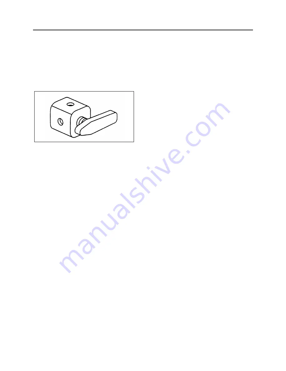
24. EMERGENCY BI-FOLD ENTRANCE
DOOR OPENING VALVES
Two emergency door opening three-way valves
are installed on the coach. One is in the front
service compartment, readily accessible. The
other one is below the R.H. dashboard panel.
When used, the valve releases pressure in the
entrance door locking cylinders, thus allowing
the door to be manually opened.
FIGURE 23: THREE-WAY VALVE
12186
25. AIR SYSTEM TROUBLESHOOTING
The following list has been designed to help in
troubleshooting some of the most common
problems in the air system and main causes. For
air brakes troubleshooting, refer to “
Air Brakes
Troubleshooting”
in this section. For more
troubleshooting information, refer to the
manufacturer's brochures annexed to this
section.
Air pressure doesn't rise to, or doesn't maintain,
a normal setting:
•
Defective air gauge (registering incorrectly).
•
Excessive leaking in air system.
•
Reservoir drain cock open.
•
Governor poorly adjusted or defective.
•
Defective compressor.
•
Worn compressor or excessive wear on
piston and/or ring.
•
Air pressure rises to normal setting too
slowly.
Excessive leaking in air system:
•
Clogged engine air cleaner.
•
Worn compressor or excessive wear on
piston and/or ring.
•
Engine speed too low.
Air pressure rises above a normal setting:
•
Defective air gauge (registering incorrectly).
•
Governor poorly adjusted or defective.
•
Restriction in line between governor and
compressor unloading mechanism.
Air pressure drops quickly when engine is
stopped:
•
Leaks in compressor discharge valve.
•
Leaks in governor.
•
Leaks in air lines.
•
Leaks in air system valves.
26. BRAKE OPERATION
The vehicle braking system uses both service
and parking air-operated brakes. The air system
is divided into two independent circuits to isolate
the front axle brakes and the rear axle brakes
(drive and tag), thus providing safe brake
operation in the event that one circuit of the
system fails. The primary circuit is connected to
the drive and tag axle brakes, while the
secondary circuit is connected to the front axle
brakes. The tag axle service brakes operate only
when the axle is in the normal driving (loaded)
position. The spring-type emergency brakes are
mounted on the drive axle, and will apply
automatically if primary system pressure falls
below 40 psi (276 kPa).
Furthermore, brake application or release, which
is speed up by a pneumatic relay valve (R-12),
will start with the rear axles and be followed by
the front axle, thus providing uniform braking on a
slippery surface. The vehicle is also equipped
with an Anti-lock Brake System (ABS), detailed
later in this section.
Brake and air system maintenance consists of
periodic inspections. Check all parts for damage
and brake adjustment (refer to subsequent
headings in this section for more details). Ensure
all fasteners are tight (refer to “
Specifications"
for
recommended tightening torques).
27. AIR BRAKES
DISC BRAKES
Knorr-Bremse SN7000
disc brakes are used on
all axles. The front and drive axle discs are
actuated by 24 square inch effective area air
brake chambers, while on tag axle, the brake
Содержание X3-45 2016
Страница 4: ......
Страница 16: ...Section 00 GENERAL INFORMATION PA1593 12 FIGURE 12 METRIC US STANDARD CONVERSION TABLE 00005...
Страница 17: ...Section 00 GENERAL INFORMATION 13 PA1593 FIGURE 13 CONVERSION CHART 00006...
Страница 18: ......
Страница 26: ......
Страница 58: ......
Страница 72: ...Section 04 EXHAUST AND AFTERTREATMENT SYSTEM PA1593 14 7 TORQUE SPECIFICATIONS...
Страница 73: ...SECTION 04 EXHAUST AND AFTERTREATMENT SYSTEM PA1593 15...
Страница 74: ...Section 04 EXHAUST AND AFTERTREATMENT SYSTEM PA1593 16...
Страница 76: ......
Страница 96: ......
Страница 134: ......
Страница 176: ...SECTION 06B ELECTRICAL 38 overcurrent working Circuit 306 shorted to ground...
Страница 180: ......
Страница 202: ......
Страница 205: ...Section 09 PROPELLER SHAFT PA1593 3 FIGURE 1 PROPELLER SHAFT ASSEMBLY 09002...
Страница 256: ......
Страница 268: ......
Страница 295: ...SECTION 16 SUSPENSION PA1593 9 2 5 TORQUE SPECIFICATIONS...
Страница 296: ...Section 16 SUSPENSION PA1593 10...
Страница 297: ...Section 16 SUSPENSION PA1593 11...
Страница 314: ......
Страница 364: ...Section 18 BODY PA1593 50 6 8 BODY PANEL AND WINDOW SPACING FIGURE 45 BODY PANEL AND WINDOW SPACING TYPICAL 18631...
Страница 380: ......
Страница 388: ......
Страница 413: ...Section 22 HEATING AND AIR CONDITIONING PA1593 15 FIGURE 18 REFRIGERANT CIRCUIT CENTRAL SYSTEM...
Страница 433: ...Section 22 HEATING AND AIR CONDITIONING PA1593 35 FIGURE 36 CENTRAL HEATING SYSTEM COMPONENTS...