Section 14: STEERING
Section 14 Updated Oct.2014
X3-45 Commuter PA1593 DOB 2400-2489
13
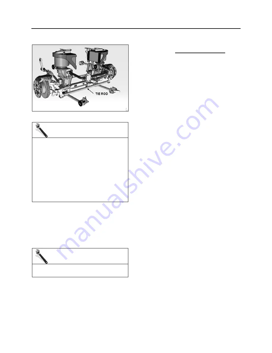
11.4 TIE ROD
FIGURE 21: TIE ROD
MAINTENANCE
Tie rod ends (ball joint) are provided with
grease fittings for pressure lubrication. These
grease fittings should be serviced every 6,250
miles (10 000 km) or every 3 months
whichever comes first.
To prevent corrosion from forming around the
ball pin, remove the old grease bead and
assure sufficient grease is applied to purge
the old grease and fill the joint and dust seal.
Good quality lithium-base mineral grease NLGI
No. 2 like Shell Retinax LX are recommended.
11.5 DRAG LINK AND TIE ROD BALL JOINTS
INSPECTION FOR CORROSION
Inspection of ball joints is important. Damaged
sealing boots, salt and climatic conditions can
cause loss of the corrosion protection coating
applied at time of manufacturing.
MAINTENANCE
Inspect drag link end and tie rod end ball joints
for corrosion once a year.
1. Carefully clean the sealing boot or dirt seal
contact area to ensure that no contaminants
can get under the sealing boot or dirt seal
during the following inspection procedure.
2. Use an appropriate inspection tool (e.g.
spatula with cut out) to push up (sealing
boot) or down (dirt seal) the seal (without
damaging it) until ball pin surface is visible.
Degrease the ball pin surface and inspect
carefully.
3. If there is corrosion of the ball pin or the
sealing boot has deteriorated through ageing
or is damaged, replace the ball joint.
4. If there is corrosion of the steering arm or tie
rod arm area which is in contact with the
sealing boot or dirt seal, clean and eliminate
all surface irregularities.
5. If there is no corrosion or damage to the
sealing boot or dirt seal, smear the steering
arm and tie rod arm with Lithium grease and
push seal back into its properly seated
position.
When dismantling tie rod or drag link, ensure
that no damage is caused to the sealing boots,
dirt seals or ball joint housings.
11.6 DROP TYPE BALL JOINT
11.6.1 Drop Type Ball Joint End Play
If end play exceeds 0.047” (1.2 mm),
readjustment is necessary.
Remove protective cap, using a suitable tool i.e.:
a 1” x 1/8” x 9” long flat bar, tighten adjuster
piece fully home (SOLID) locating thrust cup
onto ball pin.
Still with tool located on adjuster piece, back off
carefully (LEAST AMOUNT) until adjuster piece
cotter pin is allowed to pass through body, then
remove tool.
Reinstall protective cap.
Содержание X3-45 2016
Страница 4: ......
Страница 16: ...Section 00 GENERAL INFORMATION PA1593 12 FIGURE 12 METRIC US STANDARD CONVERSION TABLE 00005...
Страница 17: ...Section 00 GENERAL INFORMATION 13 PA1593 FIGURE 13 CONVERSION CHART 00006...
Страница 18: ......
Страница 26: ......
Страница 58: ......
Страница 72: ...Section 04 EXHAUST AND AFTERTREATMENT SYSTEM PA1593 14 7 TORQUE SPECIFICATIONS...
Страница 73: ...SECTION 04 EXHAUST AND AFTERTREATMENT SYSTEM PA1593 15...
Страница 74: ...Section 04 EXHAUST AND AFTERTREATMENT SYSTEM PA1593 16...
Страница 76: ......
Страница 96: ......
Страница 134: ......
Страница 176: ...SECTION 06B ELECTRICAL 38 overcurrent working Circuit 306 shorted to ground...
Страница 180: ......
Страница 202: ......
Страница 205: ...Section 09 PROPELLER SHAFT PA1593 3 FIGURE 1 PROPELLER SHAFT ASSEMBLY 09002...
Страница 256: ......
Страница 268: ......
Страница 295: ...SECTION 16 SUSPENSION PA1593 9 2 5 TORQUE SPECIFICATIONS...
Страница 296: ...Section 16 SUSPENSION PA1593 10...
Страница 297: ...Section 16 SUSPENSION PA1593 11...
Страница 314: ......
Страница 364: ...Section 18 BODY PA1593 50 6 8 BODY PANEL AND WINDOW SPACING FIGURE 45 BODY PANEL AND WINDOW SPACING TYPICAL 18631...
Страница 380: ......
Страница 388: ......
Страница 413: ...Section 22 HEATING AND AIR CONDITIONING PA1593 15 FIGURE 18 REFRIGERANT CIRCUIT CENTRAL SYSTEM...
Страница 433: ...Section 22 HEATING AND AIR CONDITIONING PA1593 35 FIGURE 36 CENTRAL HEATING SYSTEM COMPONENTS...


